SERVICE PARTS INFORMATION 3
Inverter Compressor
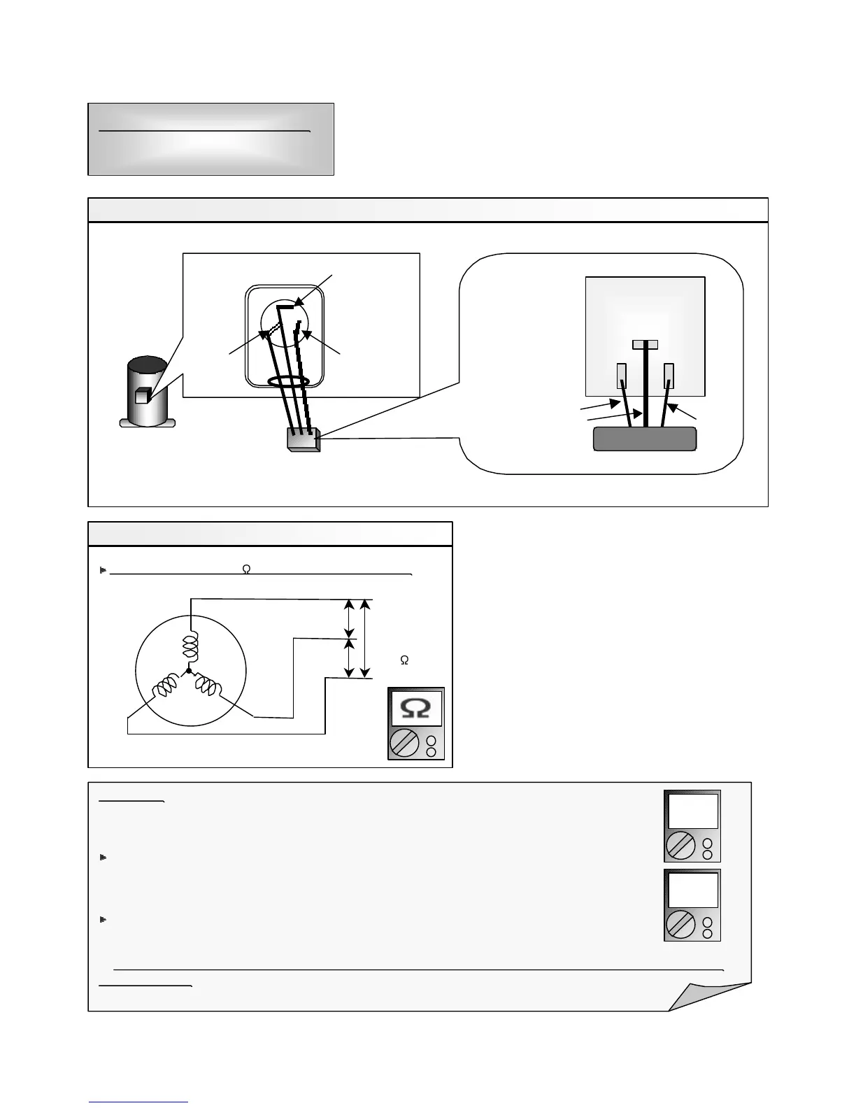
Check Point 1 : Check Connection
p Check terminal connection of Compressor (loose or incorrect wiring)
U(RED)
V (WHITE)W
(BLACK)
Terminal cover opened
INVERTER PWB
p Check connection of Inverter PCB (Loose or incorrect wiring)
Check Point 2 : Check Winding Resistance
p Check winding resistance of each terminal
If the resistance value is 0 or infinite, replace Compressor.
Resistance
Value (20 °C)
0.302
U
V
W
TB-W
TB-V
TB-U
RED
WHITE
BLACK
Attention!!
If Check 1, 2 are normal, make sure the following points.
(1) Check Voltage from Filter PCB to Inverter PCB (AC380V between each terminals of LO1, LO2, LO3).
If it does not appear, check the power supply terminal.
(2) Check Voltage from Main PCB to Inverter PCB (DC16.5V between terminals of CN32 (3-4) connector
of Main PCB).
If it does not appear, replace Main PCB.
u If both of above voltages appear, it is considered to be Inverter PCB circuit failure. Replace Inverter PCB and
check operation.
compressor
AC
DC
06-90

 Loading...