05-03
5-2-3 "COOL" Position
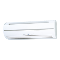
An example for COOLING TEMPERATURE CONTROL time chart (Manual setting)
When using the cooling mode, set the temperature to a value lower than the current room temperature, otherwise
the indoor unit will not start the cooling operation and only the fan will rotate.
• Indoor fan
Ts
• Opening of
EEV
100%
0%
• Refrigerant
flow
ON
OFF
ON
OFF
• Temperature
Ts + 0.5 C
TR
3Min.
Ts : Corrected setting temperature
TR : Corrected room temperature
: The thres hold temperature of start of refrigrant flow
: The thres hold temperature of stop of refrigrant flow
Ts - 0.5 C
Ts + 0.5 C
Ts - 0.5 C
Ts + 0.5 C
Ts - 0.5 C
: The thres hold temperature of start of refrigrant flow
: The thres hold temperature of stop of refrigrant flow
Ts + 0.5 C
Ts - 0.5 C
5-2-4 "FAN" Position
(1) In this position, the fan merely rotates to circulate air, so the room temperature will not change.
(2) The fan will rotate at a fan speed set with the FAN CONTROL button.
(3) When only the “FAN” mode is being used, setting the fan speed at “AUTO” is equivalent to setting it at “LOW”.
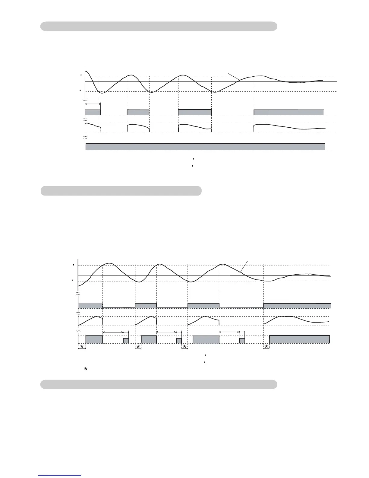
5-2-4 "HEAT" POSITION
(1) When using the heating mode, set the temperature to a value higher than the current room temperature, otherwise
the indoor unit will not start the heating operation.
(3)
An example for HEATING TEMPERATURE CONTROL time chart (Manual setting)
During defrosting, the OPERATION indicator lamp flashes 3 sec. ON and 1 sec. OFF, and repeat. The heating operation
will be temporarily interrupted.
• Indoor fan
Ts
• Opening of
EEV
100%
0%
• Refrigerant
flow
ON
OFF
ON
OFF
• Temperature
TR
4Min.
1Min.
4Min.
1Min.
4Min.
1Min.
Ts : Corrected setting temperature
TR : Corrected room temperature
: Duration of cold air prevention
(2) After the start of heating operation, the fan of indoor unit will not rotate until the heater exchange is warmed up to
blow out warm air.

 Loading...