Check Point 1 : Check connections
p Check connection of connector.
(Loose connector or open cable)
Check Point 3 : Check Voltage from Controller PCB
p Remove connector and check the voltage (AC220V).
>> If the voltage does not appear, replace Controller PCB.
Check Point 2 : Check Solenoid Coil
p Remove connector and check if coil is open.
(Normal resistance value of each coil: 1495 ± 7% )
>> If Resistance value is abnormal, replace Solenoid Coil.
SERVICE PARTS INFORMATION 8
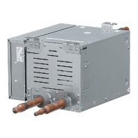
Outdoor Unit Solenoid Valve
(SV1,SV2,SV3,SV6,SV7,
SV8 ,SV8-2,SV8 -3)
Pipe (In)
Pipe (Out)
Pipe (In)
Pipe (Out)
AC AC
SOLENOIDE COIL SOLENOIDE COIL
Normal Operation
Pipe (In) TEMP. Hi,
Pipe (Out) TEMP.Normal
Protection Function
Pipe (In) TEMP. = Pipe (Out) TEMP.
Hi TEMP.
Normal TEMP.
Hi TEMP.
Hi TEMP.
OPENCLOSE
Check Point 4 : Check opening & closing operation of Valve
p Depending on either during operation or protection control, chec k if Valve is operating normally.
(When Valve opens, there is no temperature difference between Inlet and Outlet.)
(1) (2)
p If the valve closes by removing the connector of the valve
which does not close, it is considered to be Controller PCB
failure. Replace Controller PCB.
p If it does not close by removing connector, there is a
possibility of (1) clogging by dirt, or (2) deformation by
the heat at the time of Solenoid Valve installation.
In this case, replace Solenoid Valve.
AC
06-95
 Loading...
