02-30
2-3-6 Network Convertor
A U 4
Network convertor (UTR-YRDA)
Compatible indoor unit
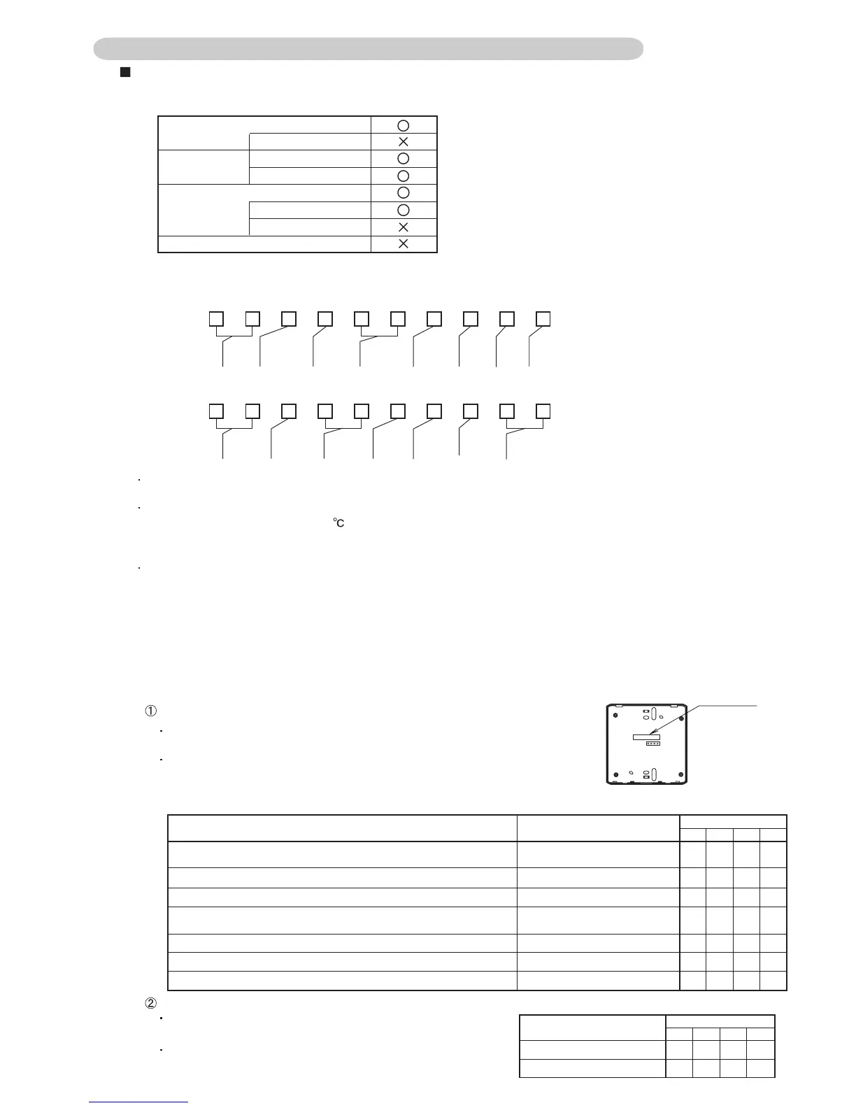
1. DIP-SW 103 <1, 2, 3, 4> RC model or system type setting
RC model
Weekly timer and heat pump model
Big multi and heat pump model
Big multi and cooling only model
Program timer and heat pump model
Program timer and cooling only model
Weekly timer and cooling only model
RC number
EZ-099DHSE-R, EZ-000DHSE-R, EZ-0001HSE-R, EZ-000GHSE-R,
EZ-00004HSE-R, EZ-00005HSE-R, EZ-0015HSE-R, EZ-0019HSE-R
EZ-0994HSE-R ,EZ-000EHSE-R
EZ-09907WSE-R, EZ-000KHSE-R, EZ-09503HSE-R, EZ-0950DHSE-R
EZ-099CWSE-R, EZ-000AWSE-R, EZ-0001WSE-R, EZ-000FWSE-R,
EZ-0012WSE-R
EZ-09906WSE-R,EZ-000BWSE-R
EZ-09907WSE-R,EZ-095YWSE-R
EZ-098VWSE-R
OFF OFF OFF OFF
DIP-SW103
1 2 3 4
DIP-SW103
Outdoor unit System type
1 2 3 4
OFF OFF OFF ON
OFF OFF ON OFF
ON OFF OFF OFF
ON OFF OFF ON
ON OFF ON OFF
ON ON OFF OFF
OFF ON OFF OFF
ON
Heat pump model
Cooling only model ON OFF ON
Rear View
RC Number
Table 1. Compatible indoor units
J-series
Big multi
Simultaneous model
Individual model
Single split type
Wired RC model
Wireless RC model
Wireless RC model
Window type
When connecting an indoor unit that has an "L" control method, connect the remote controller for VRF (UTB-*U*, UTB-*R* and
UTB-*P* ) to control from a wired remote controller. Do not connect the wired remote controller included with the indoor unit.
As the network convertor is not compatible with "Flow direction setting" (except for wired remote controller), "Anti-freeze" ,
"Filter sign", "Set temperature 10-15 "(except for models using the "U" control method), "Room temperature detection
location" (except for models using the "U" control method), "Model name display" , and "Electricity charge calculation", control
and display are not possible with the controller units.
When connecting the J-series heat pump model, the set operation conditions will be displayed on the control unit.
Therefore, the indoor unit may enter the operation standby condition as described below.
Ex. 1) If FAN setting is selected from the control unit, the LED on the indoor unit will flash and the unit will enter the operation
standby condition. Select another operation mode to clear the standby condition.
Ex. 2) If an operation mode that is different from a currently operating indoor unit is selected from the control unit, the LED on
the indoor unit will flash and the unit will enter the operation standby condition. Select the operation mode of the other
indoor unit to clear the standby condition. In addition, if operation becomes possible, such as by stopping the other indoor
units, the standby condition will be cleared and the indoor unit will automatically start operating with the selected mode.
The following indoor unit models may be controlled from a network convertor. However, the indoor unit cannot be controlled
if a wired remote controller cannot be connected to it.
1) When 4th letter is an alphabet, indoor unit models using the "N", "U" or "R" SERIES NAME.
2) When 4th letter is a figure, indoor unit models using the "L", "U" or "F" CONTROL METHOD.
A 2 L A T N
TYPE
DESTINATION
MODEL CODE
MODEL
FUNCTION
MODEL
CHANGE
CODE
MADE IN
ORIGIN
SERIES
NAME
1 2 3 4 5 6 7 8 9 10
A U
Y
Y T
2 5 L A M A
TYPE
MARKET
REGION
MODEL
CODE
FUNCTION
TYPE
CONTROL
METHOD
(REMOTE CONTROL)
MODEL
CHANGE
CODE
SPECIAL
METHOD
1 2 3 4 5 6 7 8 9 10
Set the remote controller model compatible with the number on the back of the
wired remote controller packaged with the single model or big multi model as
shown in the following Table.
Set the system type in accordance with Table to the right.
Refer to in Compatible indoor unit for information about the control method.
Indoor unit models using the "L" CONTROL METHOD
Refer to 1) and 2) in "Compatible indoor units" for
information about the CONTROL METHOD and SERIES NAME.
Indoor unit models using the "U" or "F" control method or "N", "U" or "R" SERIES NAME

 Loading...