Chapter 1: Installation and wiring
Vigilant VS1 and VS2 Technical Reference Manual 3
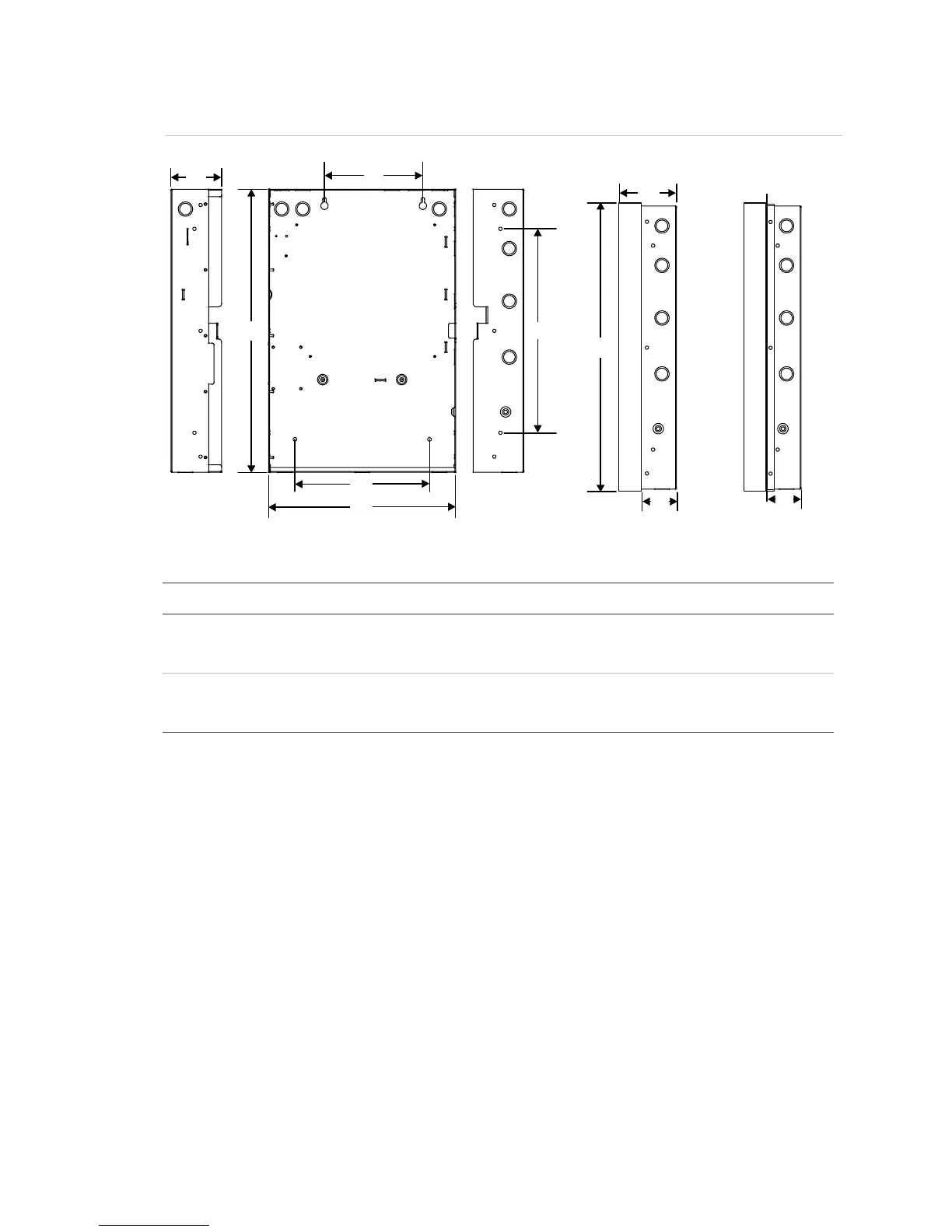
Figure 2: Cabinet backbox, backbox with door, and backbox with door and trim ring attached
D1
D2
D3
D4
D5
D6
Surface mounting holes
Semiflush mounting holes
ur
ace mounting holes
D8
D7
D9
Backbox with
door attached
Backbox with door an
trim ring attached
D9
Table 2: Backbox and backbox with door dimensions (in. and cm)
Model D1 [1] D2 D3 D4 D5 [1] D6 D7 D8 D9
VS1 21.50
(54.6)
3.85
(9.8)
7.5
(19)
15.50
(39.4)
14.25
(36.2)
10.25
(26.0)
4.9
(12.4)
23.6
(59.9)
2.7
(6.8)
VS2 28.0
(71.1)
3.85
(9.8)
9.0
(22.8)
22.0
(55.8)
15.75
(40.0)
10.25
(26.0)
4.9
(12.4)
30.1
(76.4)
2.7
(6.8)
[1] Add 1-1/2 in. (3.81 cm) to D1 and D5 dimensions for trim kit.
Panel electronics installation
The panel electronics must be installed in the cabinet box.
Note: Wait until the possibility of construction damage or vandalism has passed
before installing the panel electronics.