Chapter 1: Installation and wiring
Vigilant VS1 and VS2 Technical Reference Manual 25
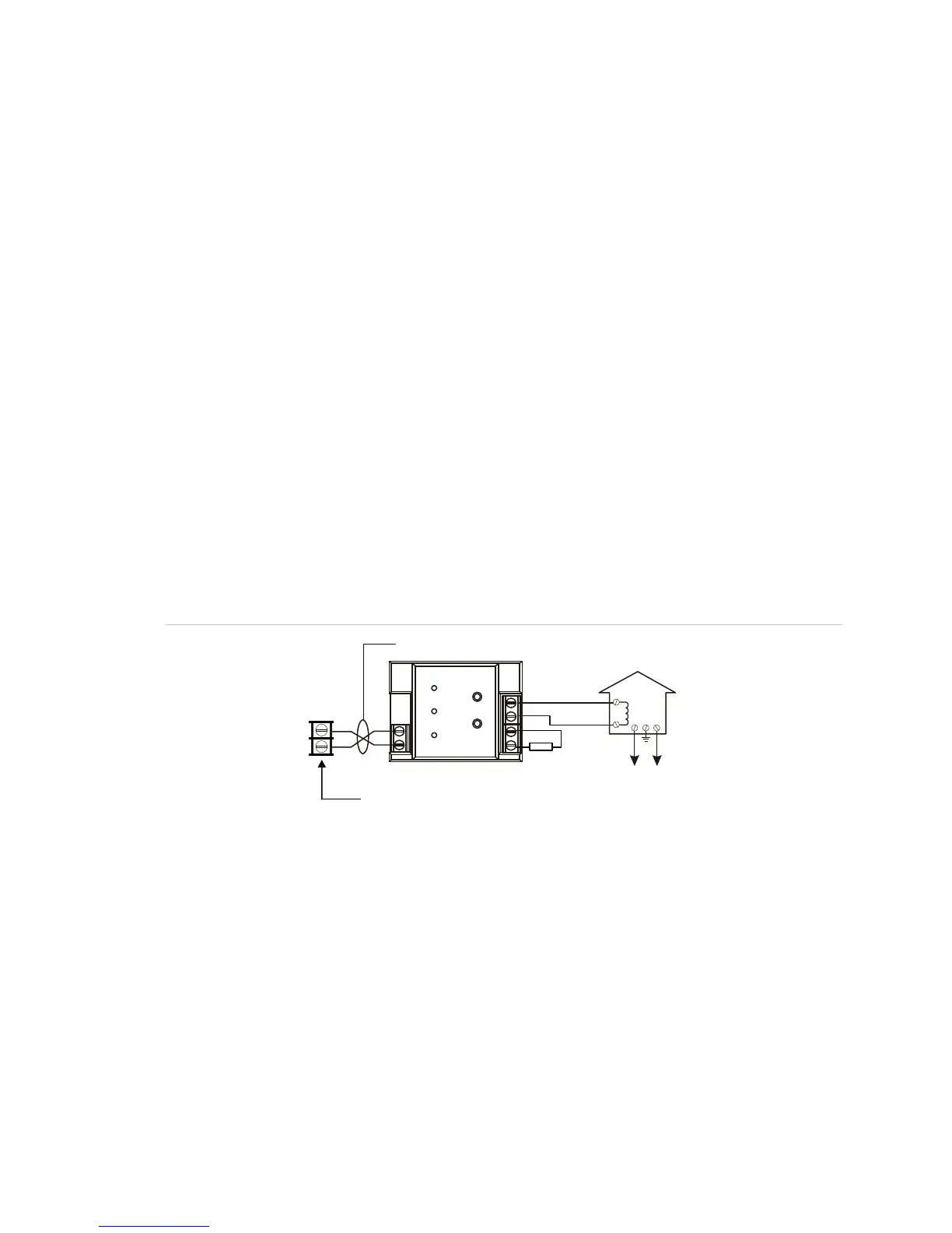
CTM module wiring
The CTM City Tie Module is an interface between the control panel notification
appliance circuit and a master box. It provides off-premises signal transmission for
systems that must comply with NFPA requirements for Auxiliary Protective Systems.
The CTM activates a local energy fire alarm box. For detailed information and wiring,
refer to the CTM Installation Sheet (P/N 3101025).
Requirements
When connecting a CTM to the panel, the following hardware and programming
requirements must be met:
• The NAC used must be dedicated to CTM use only
• All alarm zones must be programmed to activate the dedicated NAC
• The NAC used must not be programmed for signal silence
Wiring
The following wiring diagrams show how the polarity switches during an alarm
condition.
Figure 37: CTM module wiring (panel in normal condition)
Notification
appliance circui
1
1
2
2
CTM
+
+
+
+
_
_
[1] [2]
Master box
orma
con
t
on
[3]
[4]
[5]
[6]
Public fire alarm
reporting system
3
4