Chapter 1: Installation and wiring
22 Vigilant VS1 and VS2 Technical Reference Manual
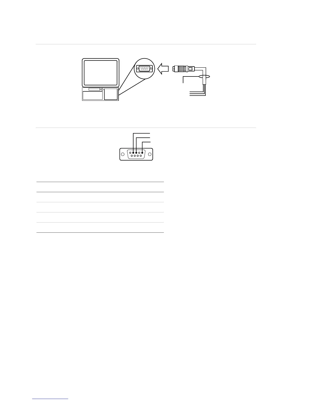
Figure 31: Computer download wiring
RS-232 cable
DB-9 female
Computer
DB-9
M port
on back of computer
To RS-232 card
Figure 32: Pin designations on female DB-9 plug (back view)
Pin 2 RXD
Pin 3 TXD
Pin 5 CO
Table 6: SA-232 card to computer DB-9 connections
SA-232 card DB-9 Description [1]
GND COM (pin 5) Black wire (ground connection)
RTS - Not used
TXD RXD (pin 2) White wire (communication)
RXD TXD (pin 3) Red wire (communication)
[1] Wire colors refer to GES Model 260097 RS-232 Cable
SA-CLA wiring
The SA-CLA card is used to supply wiring for Class A NACs and redundant Class B
remote annunciator circuits on VS1 control panels.
Circuit specifications
• Operating current
Standby: 3 mA
Alarm: 60 mA max.
• Max. resistance: 26 Ω
• Max. capacitance: 0.35 µF
• Max. current: 2.5 A per circuit