Chapter 1: Installation and wiring
26 Vigilant VS1 and VS2 Technical Reference Manual
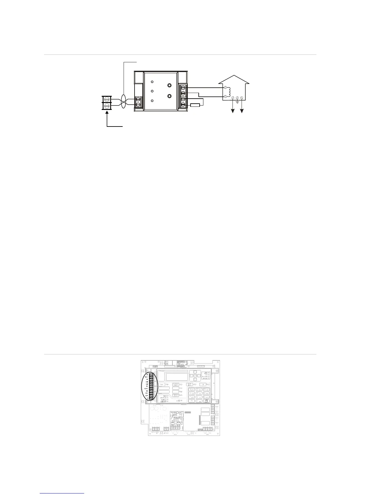
Figure 38: CTM module wiring (panel in alarm condition)
Notification
appliance circuit
1
1
2
2
CTM
+
+
+
+
_
_
[1]
[2]
Master box
Public fire alarm
reporting system
arm con
t
on
[3]
[4]
[5]
[6]
3
4
[1] 200 mA into a 14.5 Ω trip coil max. loop resistance
= 25 Ω
[2] This circuit is nonpower-limited and is supervised
for grounds and opens, but not shorts
[3] Supervised and power-limited
[4] NAC must be programmed for city tie
[5] CTM must be mounted in the same room as the
panel
[6] 15 kΩ end-of-line resistor
RPM module wiring
The Reverse Polarity Module (RPM) is an interface between the control panel and a
reverse polarity receiver. It provides off-premise signal transmission for systems that
must comply with NFPA requirements. When used as a reverse polarity remote
station transmitter, it can be connected to either a single circuit (alarm or alarm and
trouble) or up to three circuits (alarm, supervisory, and trouble). Below are application
diagrams for using the RPM module. For detailed information and wiring, refer to the
RPM Installation Sheet (P/N 3100430).
Notes
• The RPM must be mounted in conduit, in an MFC-A enclosure, immediately
adjacent to the panel.
• All relays are unsupervised and must be connected to a power-limited source.
Figure 39: Terminal wiring location