Chapter 1: Installation and wiring
Vigilant VS1 and VS2 Technical Reference Manual 27
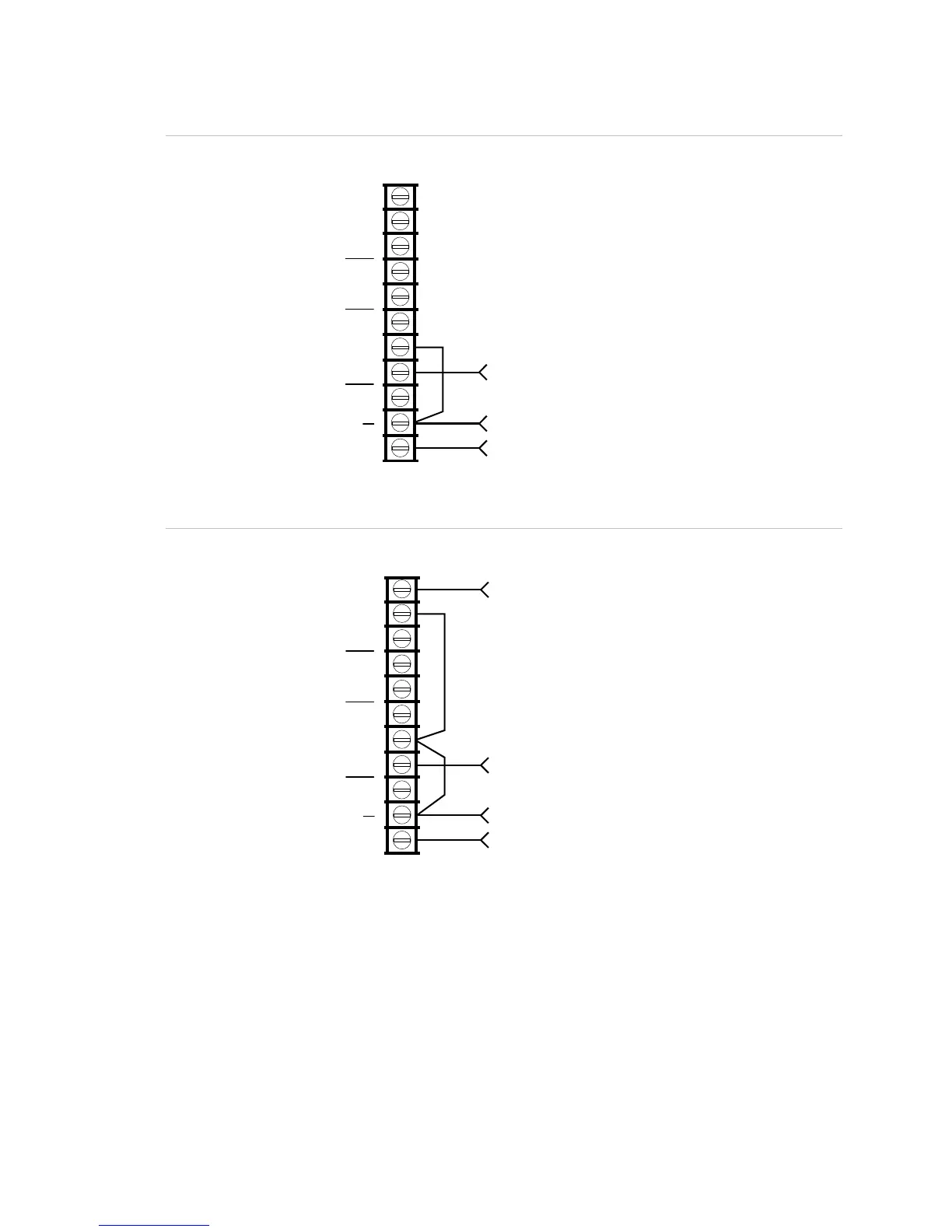
Figure 40: Alarm transmitted only
TRBL
C
NC
SUP
NC
ALM
24VOUT
ontrol panel
TB3
+
NO
From COM on RPM (black wire)
From +24 on RPM (red wire)
C
NO
+
From ALRM on RPM (brown wire
Figure 41: Alarm and trouble transmitted on a single circuit
From ALRM on RPM (brown wire)
From TRBL on RPM (yellow wire
From COM on RPM (black wire)
From +24 on RPM (red wire)
ontrol panel
TB3
TRBL
C
NC
SUP
NC
ALM
24VOUT
+
NO
C
NO
+
Note: JP1 on the RPM must be OUT.