Chapter 1: Installation and wiring
Vigilant VS1 and VS2 Technical Reference Manual 9
Vigilant VS1 panel:
3.75 A total, 2.5 A max. per circuit at 120/230 VAC 60 Hz
3.0 A total, 2.5 A max. per circuit at 230 VAC 50 Hz
Vigilant VS2 panel:
6.0 A total, 2.5 A max. per circuit at 120/230 VAC 60 Hz
5.0 A total, 2.5 A max. per circuit at 230 VAC 50 Hz
• Max. resistance: 26 Ω total
• Max. capacitance: 0.35 µF
• EOLR: 15 kΩ, 1/2 W (P/N EOL-15)
• Synchronized or not synchronized. For NACs wired Class B, signal synchronization
is supported system-wide (all NAC circuits).
• Ground fault impedance: 0 to 5 kΩ
• Power-limited and supervised
Notes
• On the Vigilant VS1 panel, Class A wiring is available only when the optional SA-
CLA expansion card is installed. Refer to the “SA-CLA Class A Interface Card
Installation Sheet” (P/N 3101094) and to the topic “SA-CLA wiring” on page 22.
• Listed EOLRs must be installed as shown for proper supervision.
• Marking indicates output signal polarity when the circuit is active. Polarity
reverses when the circuit is not active. Wire notification appliances accordingly.
Notification appliance polarity shown in active state.
• Installation limits are subject to acceptance by the Authority Having Jurisdiction
(AHJ).
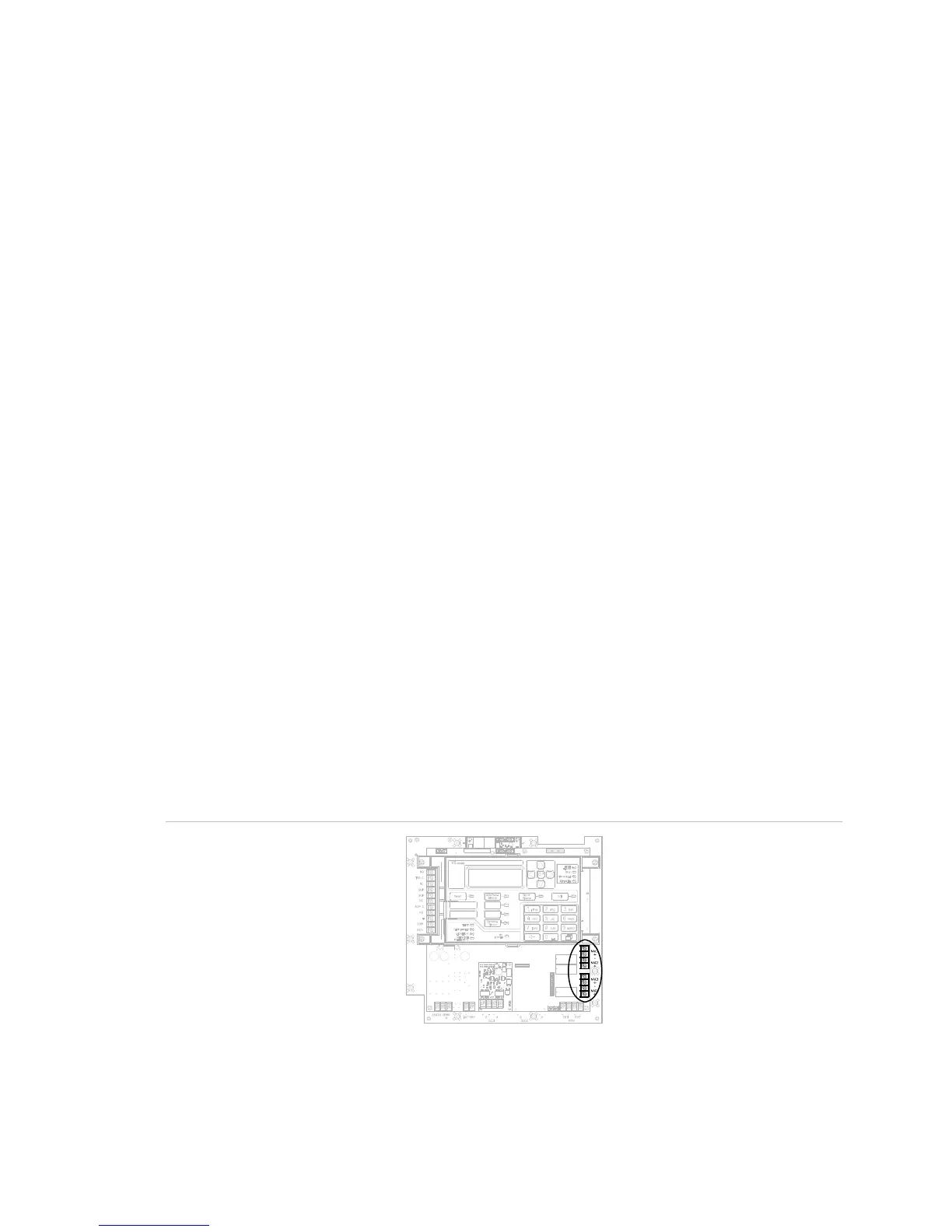
Figure 10: Terminal wiring location