Chapter 1: Installation and wiring
12 Vigilant VS1 and VS2 Technical Reference Manual
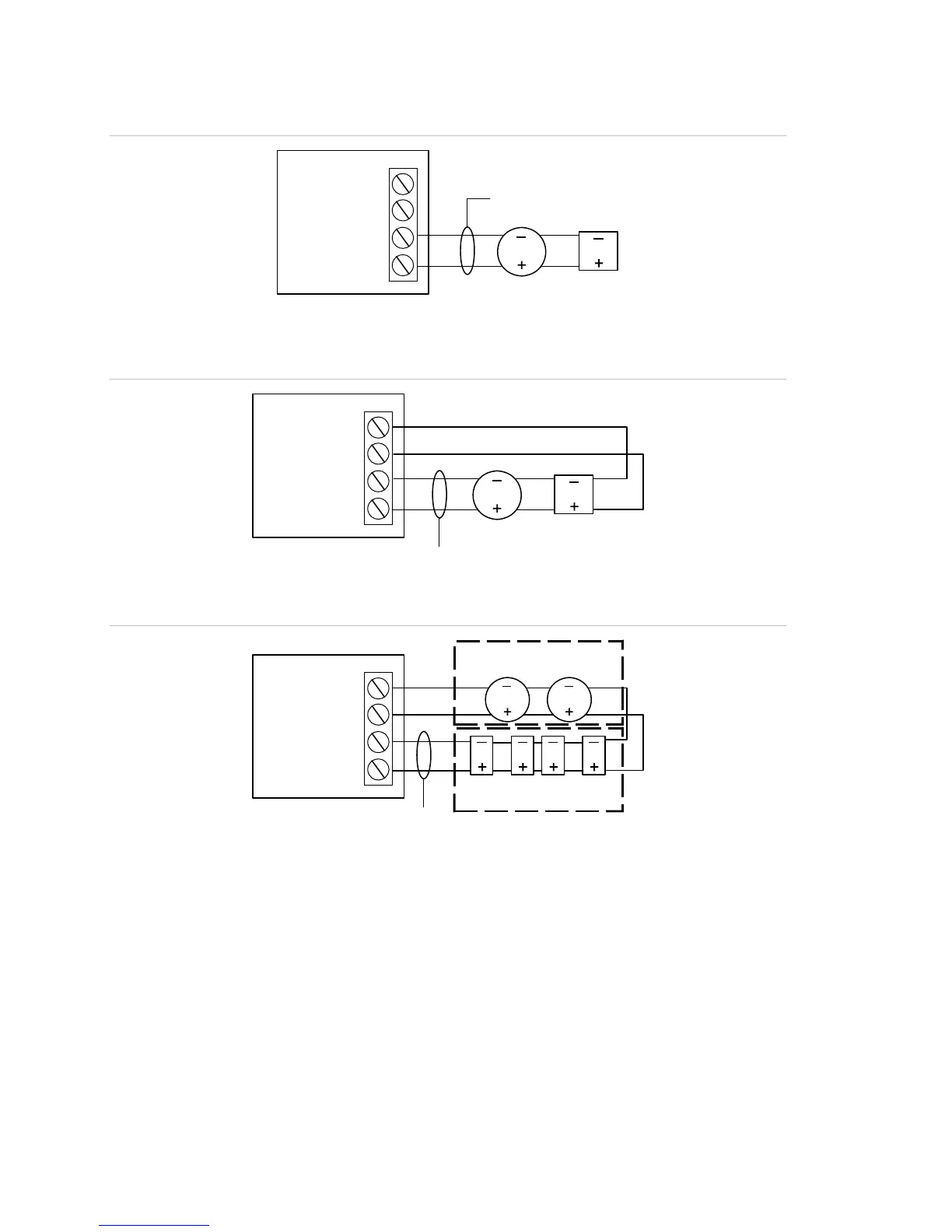
Figure 15: Class B wiring (Style 4)
Loop SEC
Loop card
+
–
Loop PRI
+
–
Loop
device
Loop
devic
Data line
Figure 16: Class A wiring (Style 6)
+
–
+
–
Loop
device
Loop
device
Loop card
Data line
Loop SEC
Loop PRI
Figure 17: Class A wiring (Style 7)
Loop SEC
+
–
Loop PRI
+
–
Loop card
Loop
devices
Isolator
module
Isolator
module
UL/ULC listed enclosure
Data line
Loop devices
with isolator base
Loop card LEDs
There are three LEDs on the card that indicate loop communication status. Primary is
the primary communication circuit. Secondary is the Class A return communication
when wiring is Class A.