Appendix D: Applications
248 Vigilant VS1 and VS2 Technical Reference Manual
• The in-suite signal silence timer expires, if programmed. (See “What is in-suite
signal silence?” on page 33 and “Programming in-suite signal silence” on page
83.)
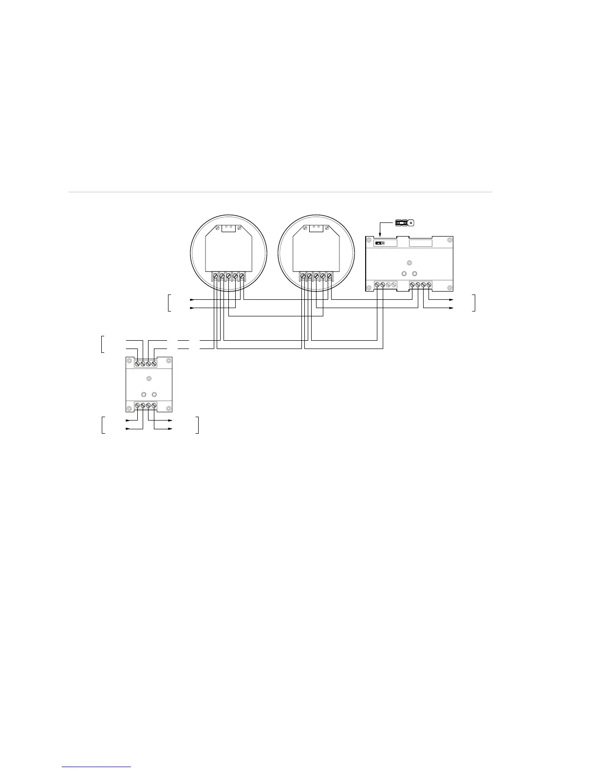
Typical wiring for zone alarm signaling
The following figure shows sounder base wiring for zone alarm signaling.
Figure 57: Typical wiring for a zone alarm signaling application
12
3
4
56
7
8
RM1
7
8
12
3
4
65
CRR
SIG+
SIG-
DATA- OUT
DATA- IN
DATA+ IN/OUT
SIG+
SIG-
DATA- OUT
DATA- IN
DATA+ IN/OUT
DATA+
DATA-
SLC
DATA+
DATA-
SLC
FIRST
DETECTOR
LAST
DETECTOR
SLC
DATA+
DATA-
DATA+
DATA-
24 VDC+
24 VDC-
UX RISER
NORMAL ACTIVE
-+
+-
SLC
N.C.
JP1: 24 VDC Monitor
• A polarity reversal module can be used to provide power to the sounder bases. You can omit the polarity reversal
module if correlation groups are used to activate the sounder bases.
• The RM1 module is used to monitor riser polarity. You can also use a CT1 module and a PAM-1 control relay for this
purpose.
Programming for zone alarm signaling
This application requires that you group detectors into zones and correlate inputs
and outputs for each zone. Zone alarm signaling is a type of correlated signaling: You
can set up a zone alarm signaling application by creating correlation groups for
specific zones. When using correlation groups, detectors are added to the input side,
and polarity reversal modules are added to the output side of one or more correlation
groups.
Note: The following instructions are written for “Zone 1” but can be applied to any
zone.