Appendix D: Applications
Vigilant VS1 and VS2 Technical Reference Manual 251
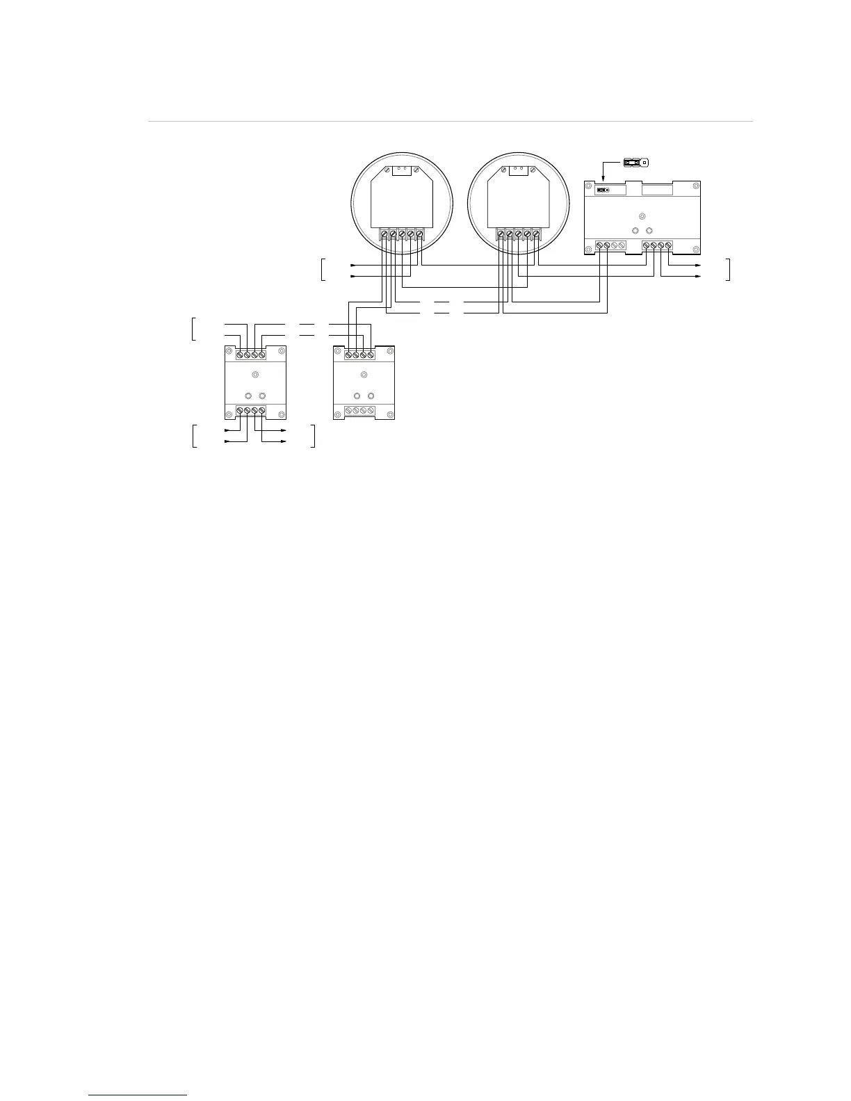
Figure 58: Typical wiring for a system alarm signaling application
12
3
4
56
7
8
RM1
SIG+
SIG-
DATA- OUT
DATA- IN
DATA+ IN/OUT
SIG+
SIG-
DATA- OUT
DATA- IN
DATA+ IN/OUT
DATA+
DATA-
SL
DATA+
DATA-
SLC
FIR
T
DETECTOR
LA
T
DETECTOR
78
12
3
4
6
5
G1M-RM
7
8
12
3
4
65
CRR
SLC
DATA+
DATA-
DATA+
DATA-
24 VDC+
24 VDC-
AUX RISER
NORMALACTIVE
-+
+-
SLC
NORMALACTIVE
-+
+-
N.C.
N.C.
JP1: 24 VDC Monitor
• A polarity reversal module can be used to provide power to the sounder bases. You can omit the polarity reversal
module if correlation groups are used to activate the sounder bases.
• The RM1 module is used to monitor riser polarity. You can also use a CT1 module and a PAM-1 control relay for this
purpose.
• The G1M-RM module is required to provide sounder synchronization.
Programming for system alarm signaling
1. Set the panel’s Event Notification option to Device.
2. Configure the smoke detectors as follows:
Message Line 1: SMOKE_<N>
Base Type: Sounder
Follow: None, Head, Alarm, Alm + Vrfy, or Alm + PreAlm
3. Configure the polarity reversal module as follows:
Device Type: Relay Silence
Message Line 1: SOUNDER_RLY_1
Message Line 2: As required
4. Configure the RM1 or CT1 module as follows:
Device type: Monitor
Message Line 1: 24VDC_RISER
Message Line 2: SOUNDER_RLY_1
5. Configure Correlation Group 001 as follows: