8-1
This section provides procedures covering the removal and installation of field servĆ
iceable parts in the handle assembly.
$ ! #
" This procedure covers removal of either the right or left sensor from the hanĆ
dle assembly.
1. Open top cover and place in position to easily access the handle assembly. Refer
to Section 5-5.
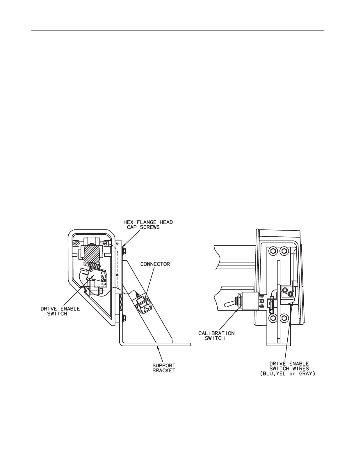
2. Disconnect connector at each end of handle assembly. See Illustration 8-1
3. Cut the two ty-raps holding wires to the angle support bracket at each end of
the Handle Assembly.
4. Remove handle assembly by removing eight hex flange head capscrews securing
it to the two support brackets. See Illustration 8-1.
ILLUSTRATION 8-1

 Loading...


