!
"
REV 5 DIRECTION 2173225-100
8-2
5. Disconnect sensor leads (red, white and black - positions 3, 4&5inconnector)
from connector. See Illustration 8-2.
ILLUSTRATION 8-2
RED
WHT
BLK
1 FROM DRIVE ENABLE SWITCH
2 FROM DRIVE ENABLE SWITCH
3 FROM SENSOR
4 FROM SENSOR
5 FROM SENSOR
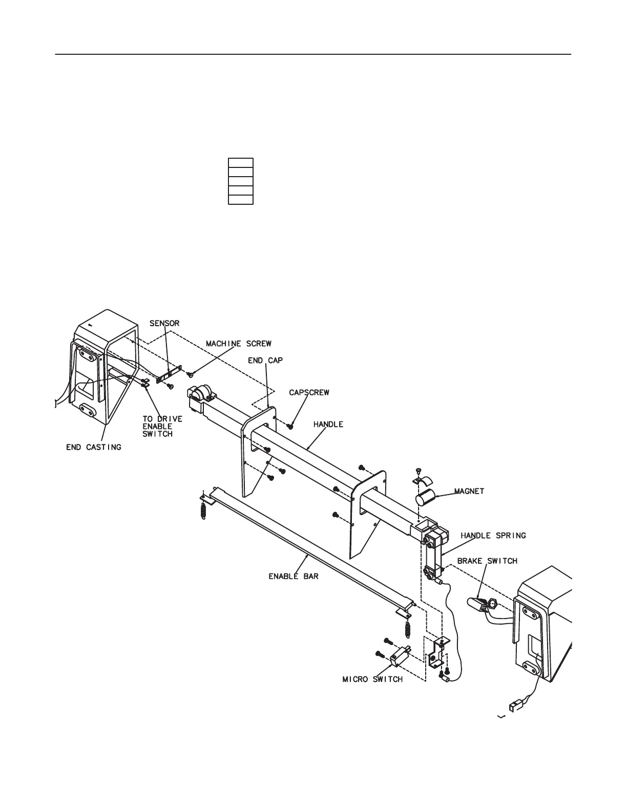
6. Detach end cap from end casting by removing four hex socket button head
capscrews. See Illustration 8-3.
ILLUSTRATION 8-3
BLU, YEL or
GRAY WIRES

 Loading...


