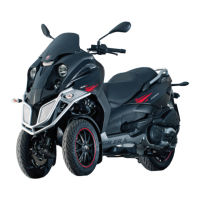
3: FUSE No. 11, 7.5A
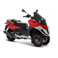
Check 7.5 A fuse No. 11 for efficiency. With inter-
face wiring disconnected from the control unit,
check the continuity of the blue - black cable be-
tween pressure sensor connector and the horn
remote control base as indicated in the photo-
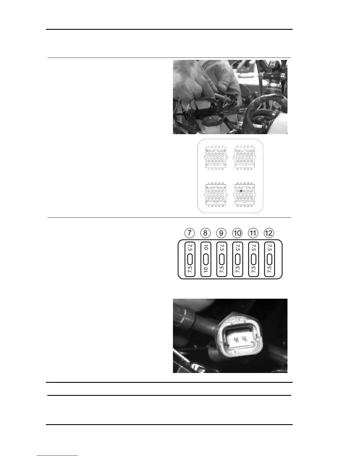
graph. Check the continuity between pin 27 and
the remote control base white cable.
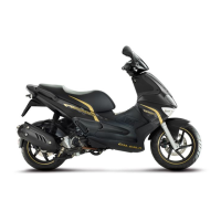
Check the continuity of the yellow-red cable be-
tween the pressure switch connector and the fuse
box (7.5A fuse No. 11) and between the remote
control base and the fuse box (7.5A fuse No. 11).
With a multimeter, also check the pressure switch
operation as well as the continuity at rest as this is
normally closed switch.
PRINCIPLE DIAGRAM FOR TILT LOCKING ELECTRICAL SYSTEM
Suspensions Fuoco 500 i.e.
SUSP - 30