EasyManua.ls Logo

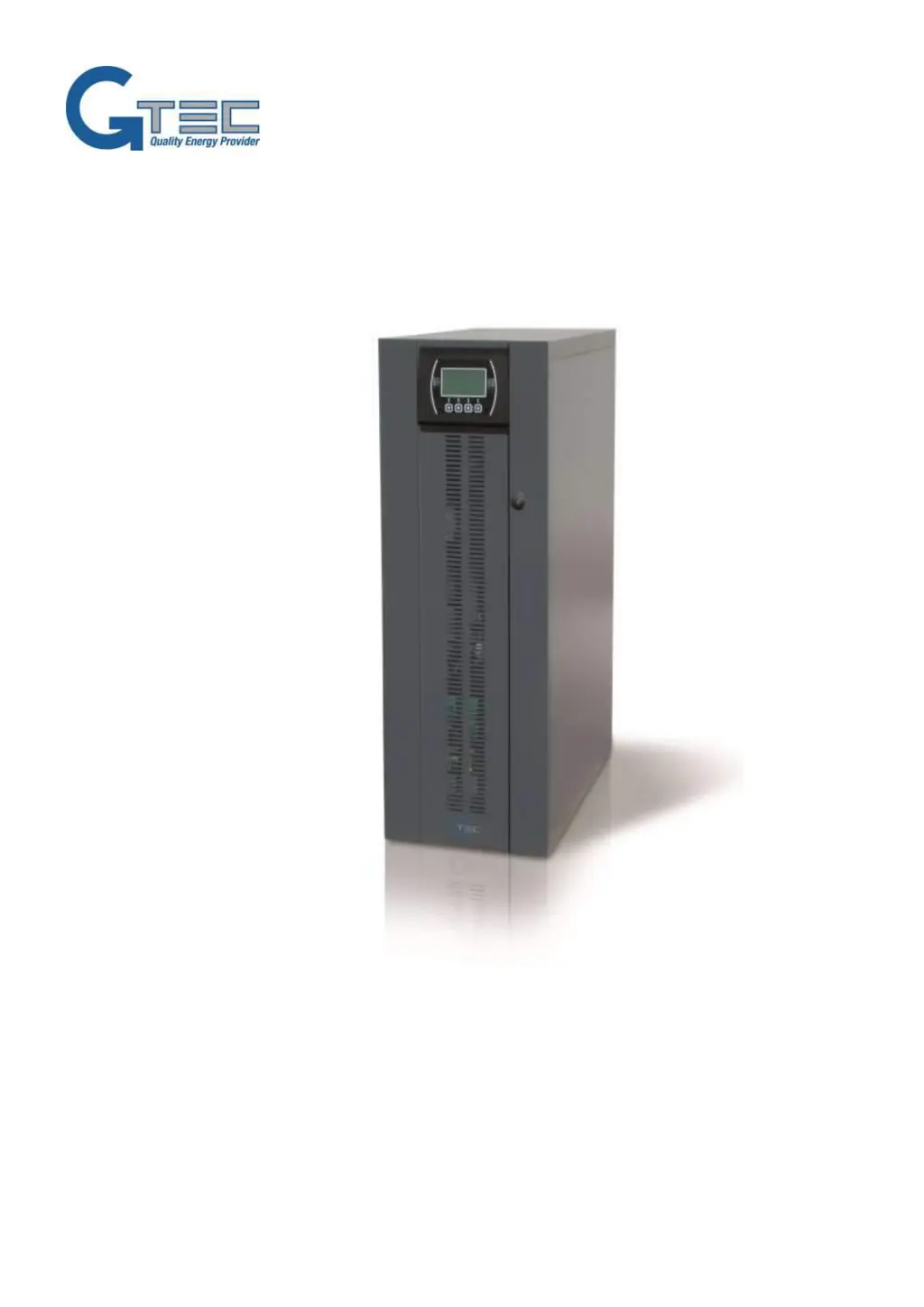
Gtec SATURN - User Manual

Default Icon
291 pages
Go to English
Print Icon
To Next Page IconTo Next Page
Loading...
1
C
C
P
P
S
S
(
(
C
C
e
e
n
n
t
t
r
r
a
a
l
l
P
P
o
o
w
w
e
e
r
r
S
S
u
u
p
p
p
p
l
l
y
y
)
)
Manuale d’uso / User Manual ( IT, GB, F, D, E )
CPS (SATURN Model)
6 - 10 - 15kVA Input 3Phases / Output 1phase
6 - 10 - 15kVA Ingresso trifase / uscita monofase

Table of Contents

Other manuals for Gtec SATURN

Questions and Answers

  • R
    ruiznatalieSep 12, 2025
    What to do if Gtec Power Supply displays code A13?
    • C
      christopher99Sep 12, 2025
      If the display on your Gtec Power Supply shows one or more of the following codes: A13, it could be due to the protection upstream of the bypass being open; restore the upstream protection, ensuring there is no overload or short circuit on the CPS output. Alternatively, the bypass switch SWBYP may be open. Close the switch located behind the door.
  • J
    Jacqueline HernandezSep 9, 2025
    What does it mean when Gtec Power Supply displays codes F42, F43, F44, L42, L43, or L44?
    • K
      Karen LittleSep 9, 2025
      If the display of your Gtec Power Supply shows one or more of the following codes: F42, F43, F44, L42, L43, L44, it indicates that the internal protection fuses on the batteries have blown.
  • R
    Regina WolfSep 8, 2025
    Why Gtec Power Supply does not start up and displays codes A30, A32, A33, A34?
    • O
      Olivia RogersSep 8, 2025
      If the display on your Gtec Power Supply shows one or more of the following codes: A30, A32, A33, A34 and the CPS does not start up, it could be because the environmental temperature is below 0°C. Heat the environment, wait until the temperature of the heat sink rises above 0°C, and then switch on the CPS.
  • R
    Richard PughAug 22, 2025
    What to do if Gtec Power Supply doesn't switch to stand-by mode?
    • S
      sarah66Aug 23, 2025
      If the Gtec Power Supply connected to the mains does not switch to standby mode, and the red LED doesn't flash, there are several potential causes. First, ensure the mains are properly connected to the input terminals, following the installation instructions. The CPS requires a neutral connection to operate; its absence can damage both the CPS and the load, so verify this connection. Check the 1/0 switch behind the door, setting it to '1' if present, and ensure the SWIN switch behind the door is closed. If there's a mains power failure, check that power is restored. Lastly, if the CPSTREAM protection device has intervened, restore it, but first verify there's no overload or short circuit on the CPS output.
  • J
    James CurtisSep 6, 2025
    What does it mean when Gtec Power Supply displays codes A26 or A27?
    • E
      Eric JohnsonSep 6, 2025
      If the display of your Gtec Power Supply shows one or more of the following codes: A26, A27, it indicates that the battery fuses are interrupted or the fuse holder switches are open. Replace the fuses or close the SWBATT switches. When replacing fuses, use others of the same type.
  • B
    Brittany RuizSep 5, 2025
    What to do if Gtec Power Supply displays F37 or L37?
    • M
      michael52Sep 5, 2025
      If the display of your Gtec Power Supply shows one or more of the following codes: F37, L37, it may be caused by several factors: the ambient temperature being over 40°C, heat sources being close to the CPS, obstructed ventilation slits, or a fault in the temperature probe or battery charger cooling system. Eliminate the cause of the overtemperature. Open the battery fuse holder isolators (SWBATT) and wait for the temperature of the battery charger heat sink to drop. Then, close the battery fuse holders.
  • M
    Mr. Edward RossSep 3, 2025
    What does it mean if my Gtec Power Supply displays codes F11, F14, F17, L06, L07, L08, L09, L14, L17, or L20?
    • J
      James StantonSep 3, 2025
      If the display of your Gtec Power Supply shows one or more of the following codes: F11, F14, F17, L06, L07, L08, L09, L14, L17, L20, it could be due to the insertion of faulty loads. Disconnect the load. Insert the maintenance bypass (SWMB), switch the CPS off and then on again. Exclude the maintenance bypass. If the problem still persists, contact the nearest service centre.
  • C
    Caroline CooperSep 2, 2025
    What to do if Gtec Power Supply displays codes F03, F04, F05, A08, A09, or A10?
    • R
      Ryan BallardSep 2, 2025
      If the display of your Gtec Power Supply shows one or more of the following codes: F03, F04, F05, A08, A09, A10, it could be due to a missing connection on one or more phases; in this case, check the connections to the terminals. Alternatively, the short circuit bar might be missing for the input single-phase connection; if so, insert the bar following the instructions given in the paragraph on single-phase connections.
  • R
    Roberto RiceSep 1, 2025
    What does it mean when Gtec Power Supply displays codes A39, A40 and the battery LED is on?
    • M
      montgomerymelissaSep 1, 2025
      If the display of your Gtec Power Supply shows one or more of the following codes: A39, A40, and the red “Batteries to be replaced” LED is on, it means the batteries have failed the periodic efficiency test. The batteries should be replaced by qualified staff because they can no longer maintain the charge for a sufficient time to ensure the required autonomy.
  • T
    Timothy RobertsonAug 31, 2025
    What does C05 error mean on Gtec Power Supply?
    • J
      Jonathan PerkinsAug 31, 2025
      If the display on your Gtec Power Supply shows the code C05, it indicates that the SWMB maintenance bypass switch is closed. Open the SWMB switch located behind the door. Alternatively, the jumper might be missing from the terminals for the remote maintenance bypass (J10). If so, insert the jumper.

Summary

INSTALLATION

STORING THE CPS AND THE BATTERY BOX

Conditions for storing the CPS and battery box.

PREPARING FOR INSTALLATION

Preliminary information and requirements for installation preparation.

INSTALLATION ENVIRONMENT

Guidelines for choosing a suitable installation site and ambient conditions.

INTERNAL BATTERIES (FOR CPS 6 - 10 ONLY)

Safety precautions and procedures for internal batteries.

INSTALLING THE CPS AND THE BATTERY BOX

Key considerations for physically installing the CPS and battery box.

ELECTRICAL CONNECTIONS

WIRING DIAGRAMS FOR CONNECTING TO THE ELECTRICAL SYSTEM

Diagrams illustrating electrical system connection methods.

INTERNAL PROTECTIVE DEVICES OF THE CPS

Details on internal fuses and isolators.

EXTERNAL PROTECTIVE DEVICES

Information on external protective devices and magnetothermal switches.

CONNECTIONS

CROSS SECTION OF THE CABLES

Table specifying minimum cable cross-sections for connections.

CONNECTING THE BATTERY BOX TO THE CPS

CPS POWER-OFF PROCEDURE:

Steps to safely power off the CPS before connecting the battery box.

CONNECTING THE BATTERY BOX:

Procedure for connecting the battery box to the CPS.

USE

PRELIMINARY OPERATIONS

Essential checks and steps before powering on the CPS.

POWERING ON FOR THE FIRST TIME

Step-by-step guide for initial CPS power-on.

POWERING OFF THE CPS

Instructions for safely powering off the CPS.

CONFIGURING THE CPS

CONFIGURATION

Options for configuring CPS parameters via software.

DEFAULT CONFIGURATION

Pre-defined default settings for the CPS.

TROUBLESHOOTING GUIDE

STATUS; ALARM CODES

TECHNICAL DATA

Input

Technical specifications for the input stage.

Output

Technical specifications for the output stage.

Battery Charger

Technical specifications for the battery charger.

Dimensions and weight

Physical dimensions and weight of the CPS.

Modes and efficiency values

Operating modes and efficiency values.

Miscellaneous

Noise, color, and ambient temperature.

Gtec SATURN Specifications

General IconGeneral
BrandGtec
ModelSATURN
CategoryUPS
LanguageEnglish

Related product manuals