Page 149 Issue 08/2013
Options and accessories
MMI with radio modem
11.1.2 Displays on the MMI
The MMI indicates all operating and fault states of the iMALPA system using
LEDs.
Ö MMI operating- and fault displays, page99
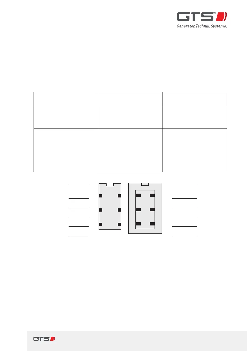
11.1.3 Plug connections, MMI and radio modem
Plug connection Socket on MMI or
radio modem
Connector on the
connection cable
Radio modem
RS232interface to
switch box
HARTING
STAF 6STI-S
HARTING
HAN 3A-GW-PG11
STAF 6FE-L
MMI
Connection for the
control button and
voltage supply
Hirschmann
ELST 412PG9, 4-pole
Hirschmann ELWIKA-KV
4412, 4-pole, 5m cable
(Special cable on
request for the power
supply with aconnector
for acigarette lighter)
RTS data
input
ws
1
63
52
41
63
52
41
1
sw
RTS data
input
UART data
bn
2 2
gr
UART data
UART data
gn
3 3
bl
UART data
GND
ge
4 4
gn/ge
GND
+15V Input
gr
5 5
br
+15V Input
GND
rs
6 6
Shielding
GND
Fig. 35 Assignment, RS232interface radio modem to switch box