Issue 08/2013 Page 32
MAPLA- Modular energy supply system for load lifting magnets
iMAPLA system description
MMI control unit (stand-alone version)
4.6.4 Installation
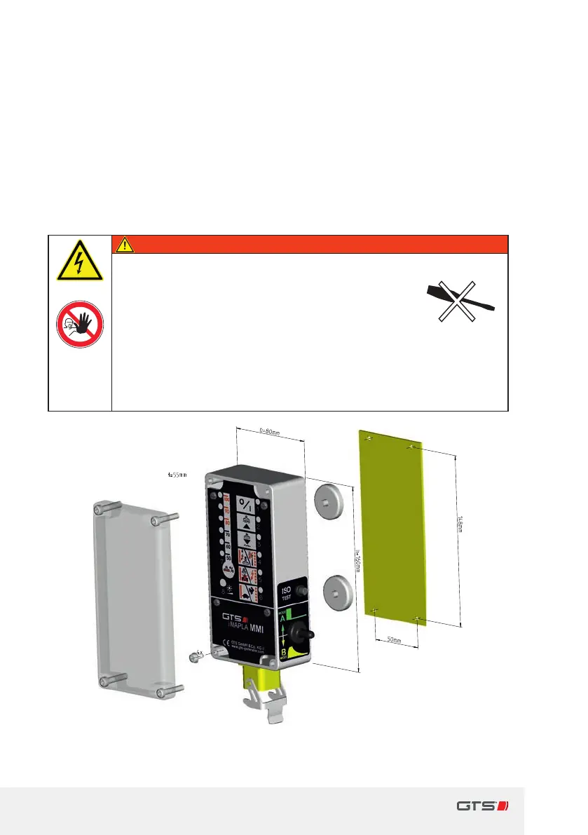
The MMI is installed inside the cab within the driver's eld of vision to allow
him/her to monitor the indicated operating states.
> Either screw on with 4screws or secure with the aid of apermanently
magnetised plate axed to the reverse side.
Ö Fig. 8, MMI dimensions and fastening dimensions (stand-alone version),
page32.
Danger
Risk of injury and risk of damage!
y
Opening or disassembling the iMAPLA system
puts the system at risk and compromises the
safety of the user.
► Do not open or dismantle the iMAPLA system!
► The iMAPLA system may only be opened by the
manufacturer or aparty authorised by it.
► Only carry out the work described in this manual.
Fig. 8 MMI dimensions and fastening dimensions (stand-alone
version)