Page 39 Issue 08/2013
iMAPLA system description
Generator and controller
The MMI interface is standardised by GTS on all switch boxes and is
backwards-compatible. An old MMI and the system tester can be connected
to the MAPLA, iMAPLA and the new iMAPLA 2013series.
Warning
Risk of accident if the lifting magnet is connected
incorrectly!
y
If the potential connection is missing, insulation faults may
not be detected by an installed insulation monitor.
► Always make sure that the PE/PA connection (potential
connection, usually green/yellow) between the lifting
magnet and generator controller is connected to the
electricity supply. The reliable detection of external ISO
errors in the lifting magnet is only possible when the
connection is active.
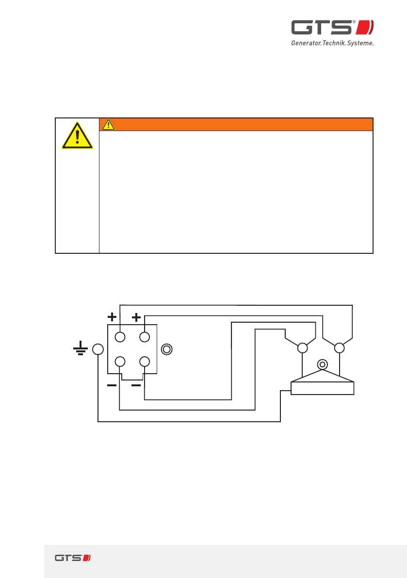
Load cable (s) to the magnet Lifting magnet
black
Gray
brown
blue
gn/ge
Fig. 14 Connection assignment at the lifting magnet output,
iMAPLA8to iMAPLA 20