Issue 08/2013 Page 82
MAPLA- Modular energy supply system for load lifting magnets
Installation and commissioning
Generator installation for iMAPLA 25and 30
5.6.3 Assembly (iMAPLA 25and 30)
During assembly, observe the minimum clearances and specications for
cooling in the following chapter.
Generator dimensions
Ö Minimum clearances and cooling provisions, page82
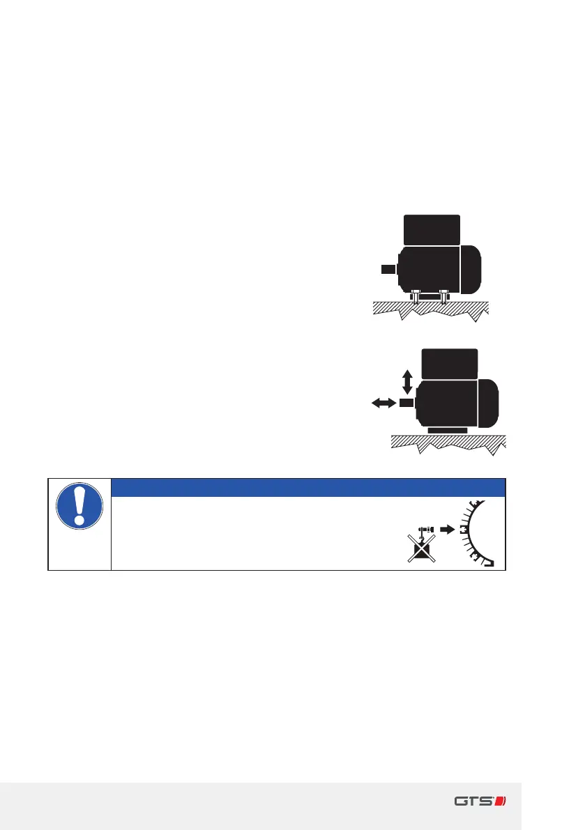
Secure the generator with at least four mounting
screws (minimum M12or comparable, bolt grade
min.8.8). The attachment must be permanent
and resistant to shock and vibrations. Use
suitable means to prevent the screws from
coming undone by themselves, e.g.via atension
ring according to DIN 128.
y Tightening torque for mounting screws: M=
87Nm
y Permissible load of the shaft: Fr
max
= 5,000N
(measured in 60mm axial clearance from the
point where the shaft exits the bearing plate)
Fa
max
= 500N
Important
► Do not attach any third party parts to
the mounting proles on the generator
housing.
5.6.4 Minimum clearances and cooling provisions
y The generator needs sucient ventilation for cooling. The cooling air is
drawn through the cooling proles by the fan wheel on the rear side of the
generator and across the housing, towards the front side.
y Ensure adequate air feed and exhaust openings.
y Comply with the following minimum clearances and note the regulations
for cooling.
4Mounting screws
Fr
Fa
max
max