Issue 08/2013 Page 64
MAPLA- Modular energy supply system for load lifting magnets
Installation and commissioning
Installation of MMI
Construction type “External Unit” and Stand-Alone MMI
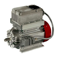
y iMAPLA Generator
y Switch box
y MMI
y Connection cable, MMI switch box
y Connection cable, switch box lifting magnet
y Connection cable, MMI to control button
Construction type “External Unit” and MMI with radio modem
y iMAPLA Generator
y Switch box
y MMI with radio modem
y Connection cable, switch box radio modem
y Connection cable, switch box lifting magnet
y Connection cable MMI to the control button/voltage supply
5.3 Installation of MMI
For information about the MMI installation, see the description of the MMI
used.
Ö MMI plug connections (default assignment), page31 for stand-alone
MMI
Ö MMI with radio modem, page147
5.4 Installation of cables
Before the installation of cables, carefully read the entire chapter as well as
the safety instructions in Chapter 2and follow the given instructions and
regulations.
Ö Safety instructions, page10
Connection and pin assignment
Ö Overview of cables, System overview, page19.
Ö Plug connections on the generator and switch box, page37
Ö MMI control unit (stand-alone version), page29
Ö Plug connections, MMI and radio modem, page149