Issue 08/2013 Page 88
MAPLA- Modular energy supply system for load lifting magnets
Installation and commissioning
Generator installation for iMAPLA 25and 30
Assembly
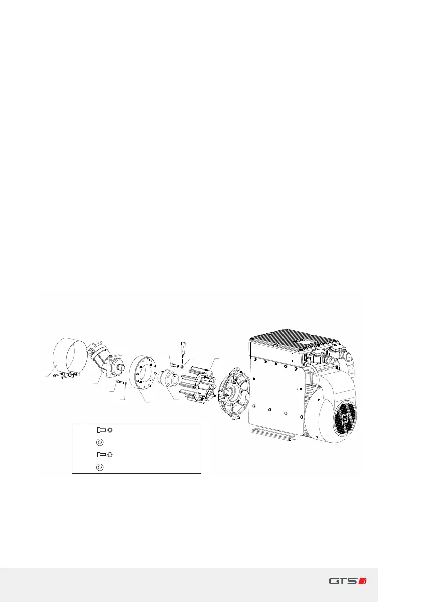
Ö Fig. 32, Assembly of ange mount hydraulic drive (iMAPLA25and 30),
page88
> Place the ange[1] onto the generator and secure with four screws[2a].
Place atoothed washer[2b] underneath the screws and secure with
Loctite.
> Mount the rst half of the coupling[3] on the shaft at the generator and
prevent it from twisting on the shaft using with akey.
> Mount the washer [4] onto the hydraulic motor [6].
> Place the second half of the coupling[3] to the hydraulic motor.
> Place the hydraulic motor [6] with washer [4] and second half of the
coupling to the generator. Where necessary, turn the coupling slightly to
ensure the gearing locks.
> Place toothed washers[5b] to eight screws[5a] and secure disk[4] to the
ange[1].
> Place the collar[7] onto the coupling unit and tighten rmly with two
screws.
8x
4x
2a
2b
5a
5b
M12x40 DIN
912
DIN
128 A-12
M8x30 DIN
912
DIN
128 A-8
7
6
5a
5b
4
3
2a
2b
1
2a M12x 40DIN 912
2b
A-12DIN 128
5a
M8x 30DIN 912
5b
A-8DIN 128
Fig. 32 Assembly of ange mount hydraulic drive (iMAPLA25and 30)
 Loading...