Issue 08/2013 Page 80
MAPLA- Modular energy supply system for load lifting magnets
Installation and commissioning
Generator installation for iMAPLA 25and 30
5.6.1 Requirements on the installation position
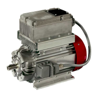
iMAPLA Generators “One Unit” construction type
with attached switch box
y Do not assemble the “One Unit” type in the engine compartment.
iMAPLA Generators “External Unit” construction type
with aseparate switch box
y Do not expose the External Unit type to the radiation range of heat
sources (e.g.exhaust pipes). If no other installation site is available, the
generator must be isolated from radiant heat using suitable insulation- or
bulkhead plates.
y The ow of cooling air in the generator must not be deected or restricted
by the ow of air in the main fan of the engine.
y The generator switch box must be situated outside the engine
compartment.
y The iMAPLA generator is protected against spray water according to
IP54and may also be secured to the outside of the vehicle.
y The rotational direction of the generator is not important for its operation.
It can be operated in the clockwise- and anti-clockwise direction.
Install the generator safely and securely on a100 % level surface with
aload-bearing capacity adequate for the weight class of the generator.
Mount generators with abelt drive on rails or provide other means for
adjusting the belt tension.
Important
y Install the generator in away which makes accidental spraying
with high-pressure cleaners impossible.
y The installation site must be low-vibration.
y Choose an installation location through which it is ensured
that sucient ventilation is provided at all times, where, if
possible, the cooling air temperature does not exceed 40°C.