Page 31 Issue 08/2013
iMAPLA system description
MMI control unit (stand-alone version)
Description of the individual displays
Ö MMI operating- and fault displays, page99
Summary of display values and fault blank codes for error localisation in the
event of asystem fault
Ö System fault, page121
Ö Troubleshooting, page116
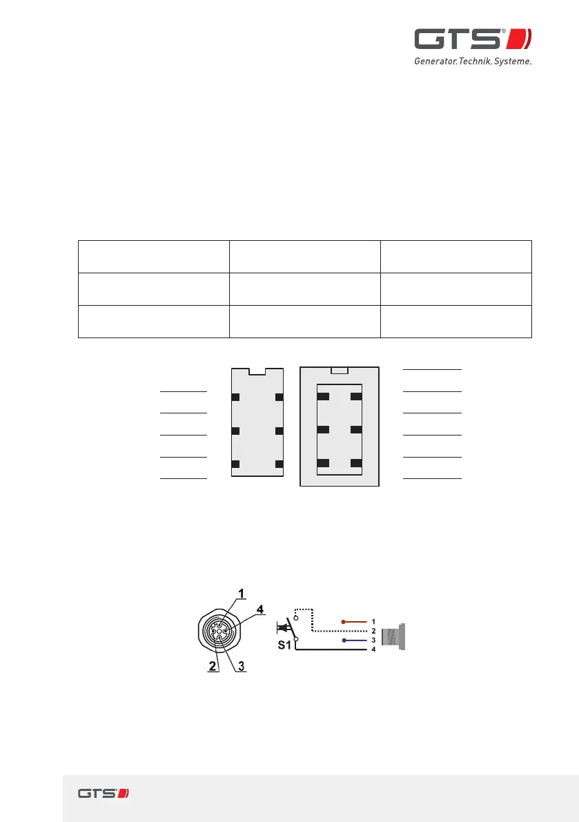
4.6.3 MMI plug connections (default assignment)
Plug connection Socket on MMI Connector on the
connection cable
RS232interface to
thegenerator
HARTING
STAF 6STI-S
HARTING HAN
3A-GW-PG11
Connection for
thecontrol button
Hirschmann
ELST 412PG9, 4-pole
Hirschmann ELWIKA-KV
4412, 4-pole, 5m cable
Free 1
63
52
41
63
52
41
1
BK
Free
UART data
BN
2 2
GY
UART data
UART data
GN
3 3
BU
UART data
GND
YE
4 4
GNYE
GND
+15V Input
GY
5 5
BN
+15V Input
GND
PK
6 6
Shielding
GND
Fig. 6 Assignment of the RS232interface on the MMI STD to the switch
box
Socket on MMI type STD Connection cable to the control button
1 A/B switch INPUT 1 brown (not in use)
2 Joystick S1INPUT 2 white (Joystick
S1Input)
3 GND MMI 3 blue (not in use)
4 +12V OUTPUT (S1) 4 black
(Joystick +12V Output)
Fig. 7 Connection assignment, control button
 Loading...