Issue 08/2013 Page 38
MAPLA- Modular energy supply system for load lifting magnets
iMAPLA system description
Generator and controller
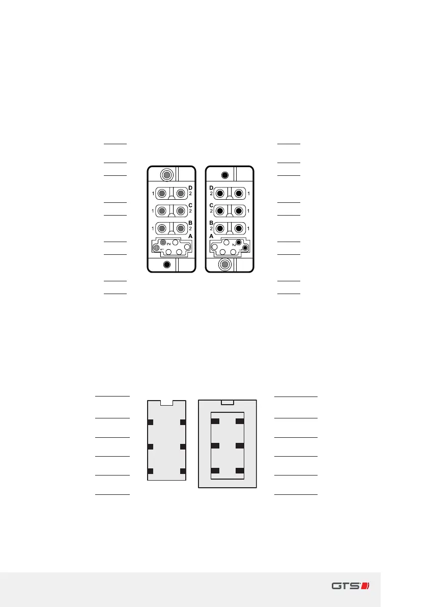
The connector assignment for 160 (BG160) model generators each with
a4-pole assignment with arated power >=25kW:
Generator Socket on
generator
Cable for
Switch box
Switch box
Housing weight PE PE Housing weight
Generator U1 D1 D1 Generator U1
Generator U2 D2 D1 Generator U2
Generator V1 C1 C1 Generator V1
Generator V2 C2 C2 Generator V2
Generator W1 B1 B1 Generator W1
Generator W2 B2 B2 Generator W2
Generator F1+ A1 A1 Generator F1+
Generator F2- A2 A2 Generator F1-
Fig. 12 iMAPLA 25and 30; plug connection generator-switch box
The 160model generator for >=25kW has two isolated 3-phase star
windings. These are kept in the switch box on two separate converters.
For example: rst winding, rst phase U1/second winding, rst phase U2etc.
RTS data
output
BK1
1
63
52
41
63
52
41
1
BK
RTS data
output
UART data BK2 2 2 GY UART data
UART data BK3 3 3 BU UART data
GND BK4 4 4 GNYE GND
+15V Input BK5 5 5 BN +15V Input
GND BK6 6 6 Shielding GND
Fig. 13 Assignment of RS232interface to MMI on switch box