Page 77 Issue 08/2013
Installation and commissioning
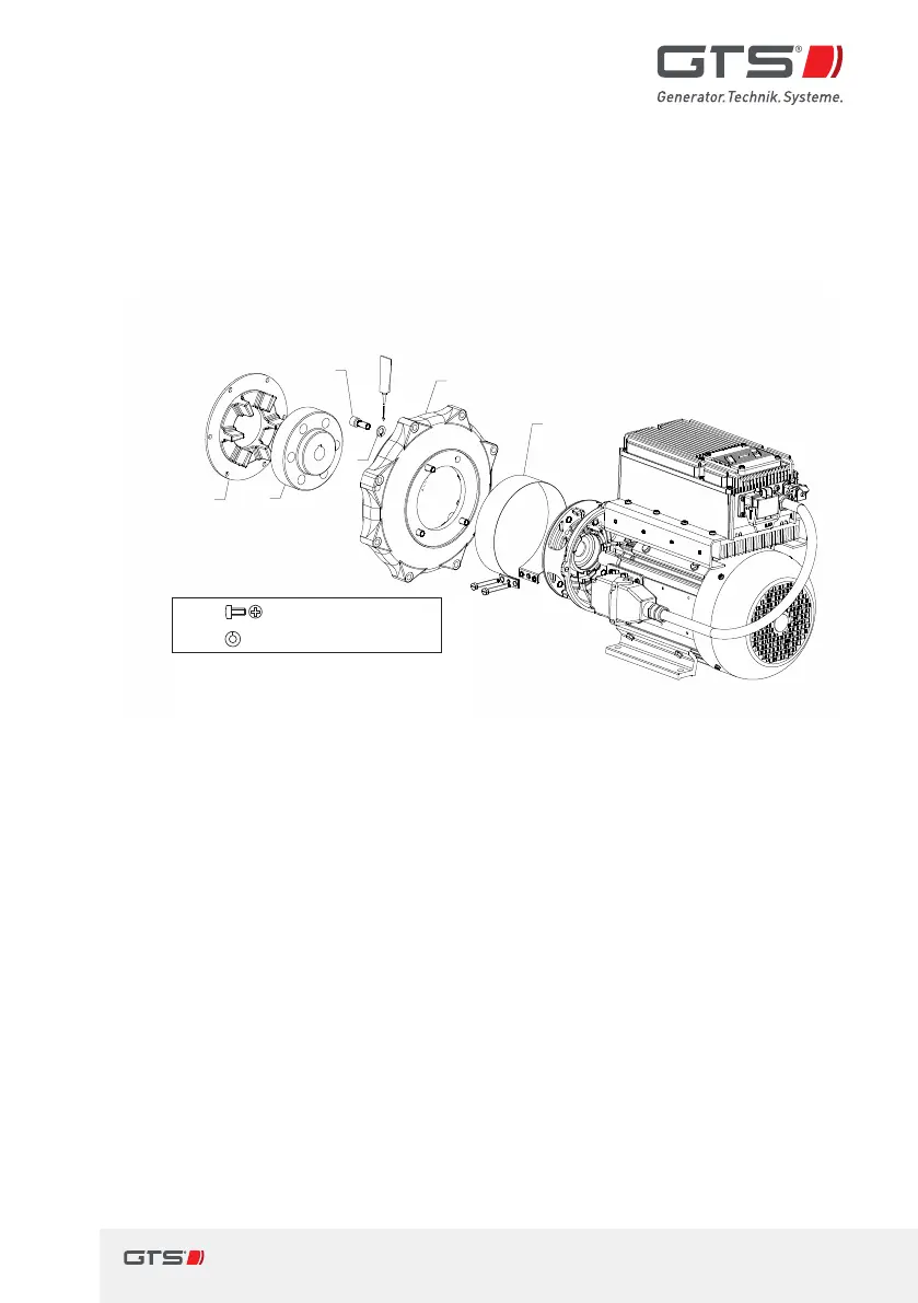
Generator installation for iMAPLA 8, 13, 17and 20
> Secure the drive side of the coupling[6] to the drive and insert it into the
coupling plate. If necessary, while inserting, twist slightly until the gearing
locks.
> Secure the ange[1] to the drive unit.
4b
M12x30
DIN912
DIN128
A-12
6
5
4a(4x)
4b
1
2
4a
4a M12x 30DIN 912
4b
DIN 128A-12
Fig. 28 Assembly of ange mount SAE5 (iMAPLA 8,13,17and 20)
5.5.7 Assembly instructions for hydraulic drive
Preparatory disassembly
> Carry out the preparatory disassembly on the generator.
Ö Assembly instructions for ange mount SAE5, page76