Page 33 Issue 08/2013
iMAPLA system description
Generator and controller
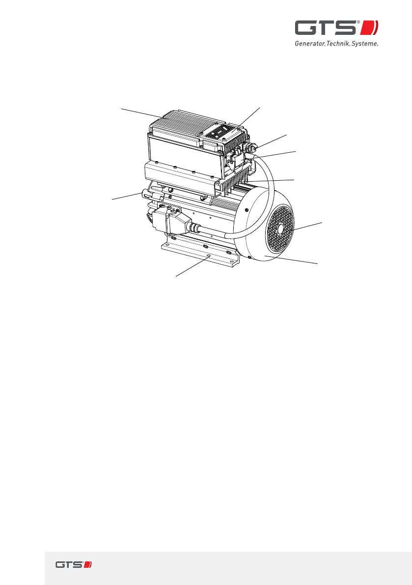
4.7 Generator and controller
1
9
8
2
3
4
5
6
7
1
Switch boxes with control electronics (completely cast)
2
iMAPLA: generator controller
iMAPLA series 2013: insulation monitor (fully cast)
3
Connection for MMI (RS232interface)
4
Connection for lifting magnet
5
Cooling element for the switch box
6
Cooling air inlet
7
Fan wheel cover
8
Attachment bracket (both sides)
9
Drive shaft
Fig. 9 Generator iMAPLA 17 “One Unit” (example)