Page 41 Issue 08/2013
iMAPLA system description
Generator and controller
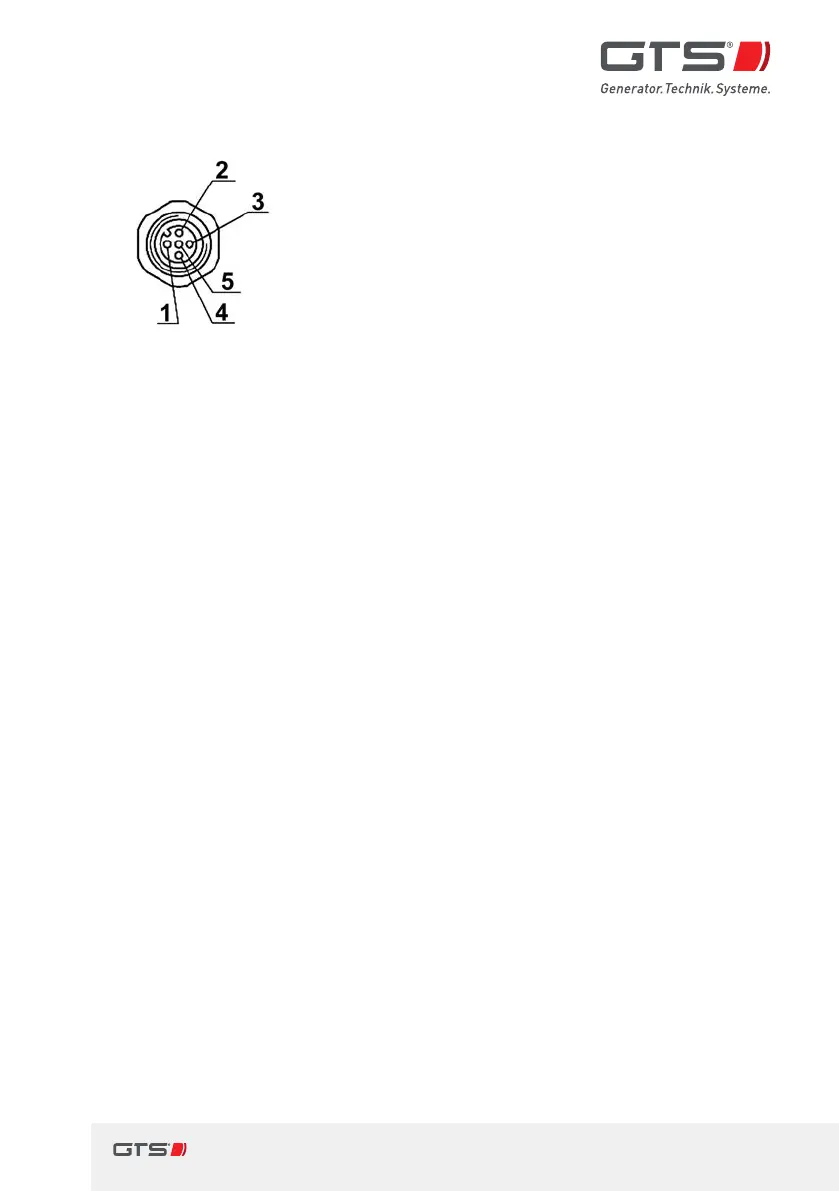
1
brown
CAN-GND (shielding)
2
white
CAN Low
3
blue
CAN High
4
black
MMI-GND Output
5
gray
MMI +15V Output
Fig. 16 Connection assignment CAN socket iMAPLA 2013series
Information about the CAN connection
y From the iMAPLA 2013series, aCAN Bus connection is also provided
alongside the MMI interface.
y The CAN connection has asealed M12 5-pin socket with Aencoding.
y The CAN Bus is isolated from the generator potential via adouble isolation
barrier.
y The CAN GND and MMI GND must be connected separately and must not
be connected together.
y By default, the CAN Bus is terminated internally with 120Ohms.
y CAN protocol according to Standard J1939 250Kbit Extended Identier.