Page 99 Issue 08/2013
Operation
MMI operating- and fault displays
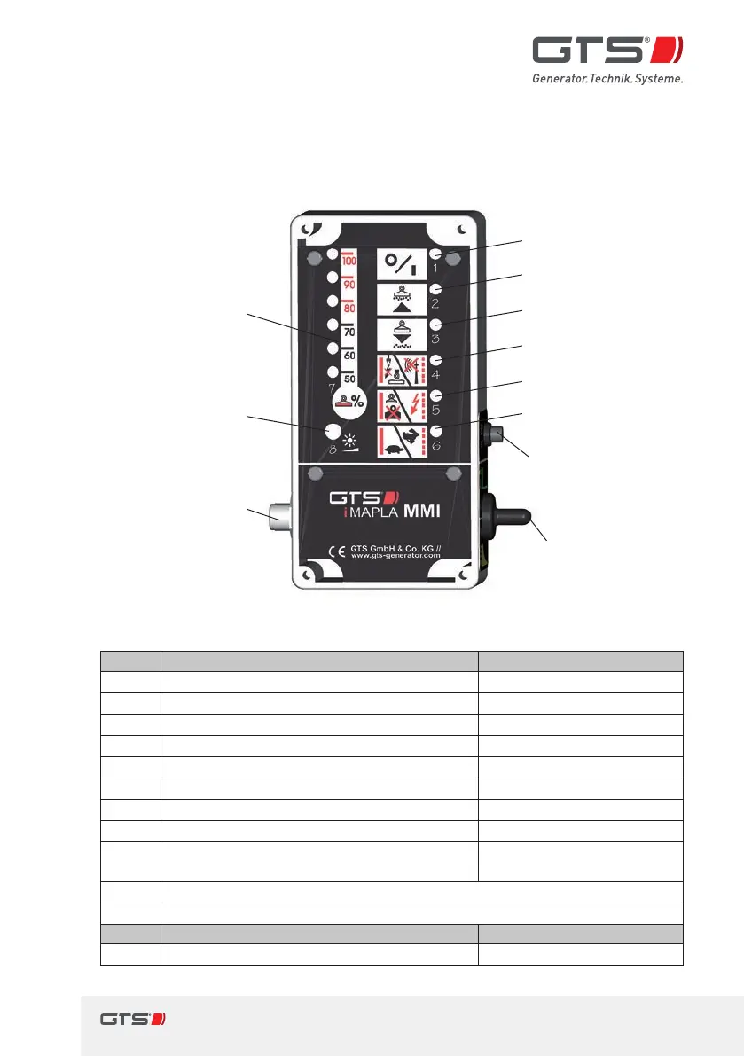
6.3 MMI operating- and fault displays
The MMI control unit indicates all operating and fault states in the iMALPA
system using LEDs.
1
2
3
4
5
6
10
7
8
9
11
Fig. 33 MMI displays
LED lit ashing
1
Operation indicator, MMI
2
Operation indicator, lifting magnet (lift)
3
Quick magnetisation running (release)
4
Interruption Interface fault
5
Overload limitation System fault
6
Underspeed Overspeed
7
Cyclic duration factor, lifting magnet
8
Light sensor for the displays
4+5+6
Temperature warning, control electronics
only when 100 %-LEDs ash at the same time
Insulation fault
9
Control button (s) connection via M12 4-pole connector
10
Check button for insulation monitor
Switch top Switch bottom
11
Normal/material handling mode[A] Sorting/Jog mode[B]