14
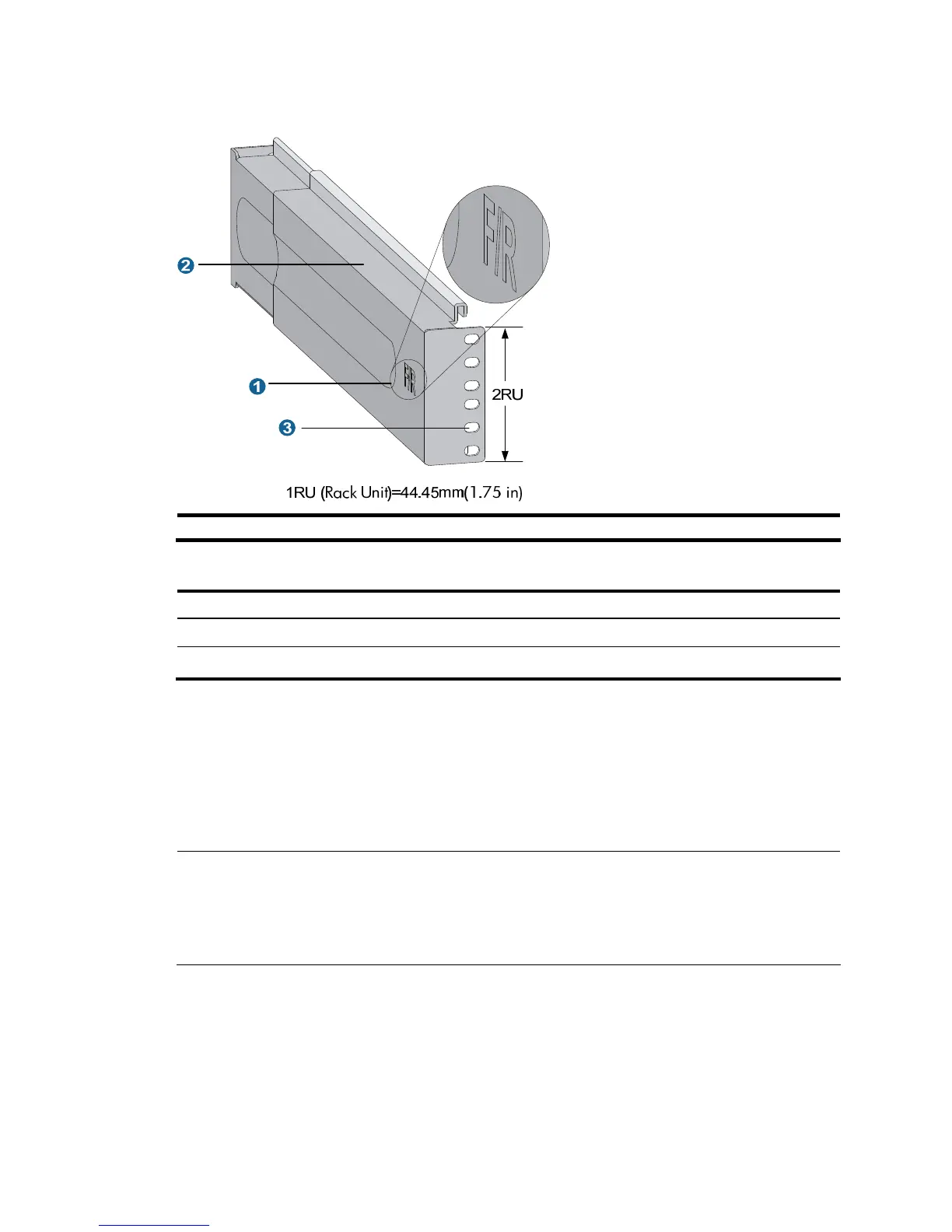
Figure 6 Right slide rail
1: Signs 2: Guide rail 3: Installation hole
Table 8 Description of signs on the slide rails
Sign Meaning Remarks
F/L Front end of the left slide rail Mount this end to the front left rack post.
F/R Front end of the right slide rail Mount this end to the front right rack post.
Step2 Mark the position on the rack for installing the slide rail.
• Make sure the bottom edge of the slide rail aligns with the middle of the narrower metal area
between holes, as shown in Figure 7.
• Each
rack post requires six screws to fix the slide rail. You only need to mark the uppermost square
hole and lowermost square hole for installation.
• Mark the square holes at the same height on the other three rack posts.
NOTE:
One rack unit has three holes, the middle of which is an auxiliary installation hole, and the other two are
standard installation holes. You can distinguish them by the space between each two holes. The space
between a standard installation hole and an auxiliary installation hole is larger than that between two
adjacent standard installation holes.

 Loading...


