Mechanical
QuantumX A03031_24_E00_01 HBM: public 51
Mounting sequence
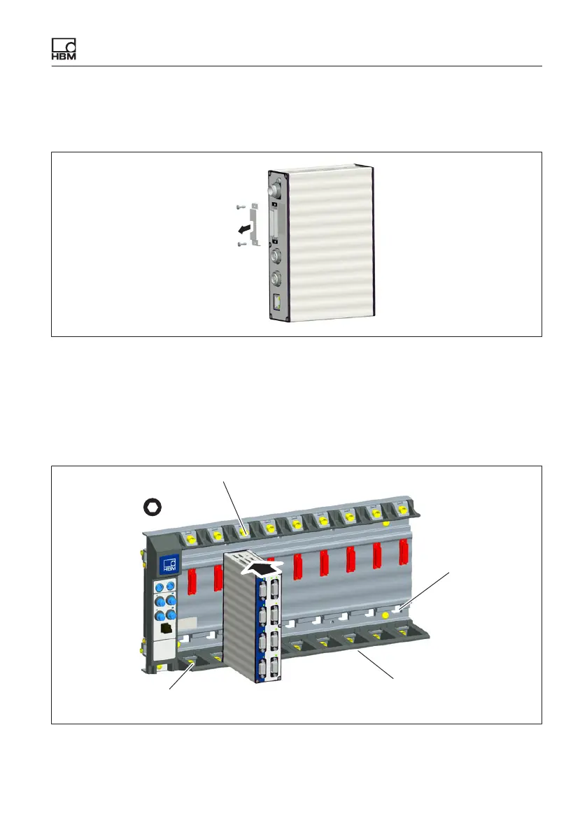
1. Remove the cover of the connecting plug (rear of module).
Cover
Fig. 6.16 Removing the cover
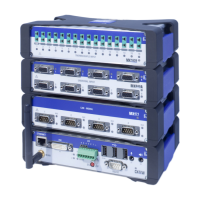
2. Unscrew the upper and lower screwed clamping glands of the backplane up
to the stop (the screws are secured against falling out!).
3. Position the module vertically on the backplane and push it in carefully on
the lower guide rail back up to the stop.
4,0 a.f.
Opening for con
nection to Ethernet
Lower screwed clamping gland
Guide rails
Upper screwed clamping gland
Fig. 6.17 Mounting the module