Connecting individual QuantumX modules
QuantumX A03031_24_E00_01 HBM: public 71
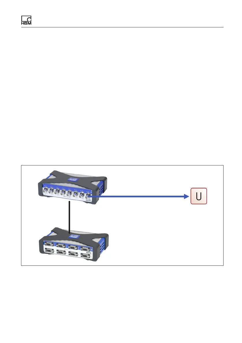
7.2.10 Output of signals with standardized voltage in real time (MX878B
or MX879B)
It is very easy to integrate QuantumX via the globally standardized interface of
a normalized voltage (+/ 10 V), particularly in a test bench environment.
MX878B or MX879B modules for distributed use serve this purpose. These
modules also allow onboard different input channel calculations, such as
matrix calculation for compensation of parasitic effects in multicomponent
transducers, ADDMUL, PID controls or limit value switches.
This mode is configured using the catman
®
or MX Assistant software. All the
modules must be connected via FireWire, and the signals to be transmitted
(analog, digital rotary encoder or digital CAN Bus signals) must be parameter
ized isochronously (realtime operation) and then assigned to the relevant ana
log voltage output. The parameterization is permanently stored in the modules
(EEPROM). The maximum measuring rate is limited to 5 kHz. The mapping of
harmonic signals up to approx. 500 Hz is excellent. Maximum bandwidths and
ultrashort latency times are achieved with MX410B.
Any measurement module in the FireWire
group, also CAN Bus MX471B.
KAB272
MX878B / MX879B
Fig. 7.10 Analog output in real time