Transducer connection
QuantumX A03031_24_E00_01 HBM: public 141
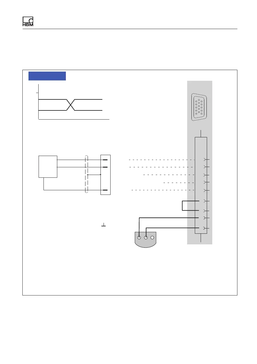
9.21 Frequency, differential, without directional signal
Supported by the following modules: MX840B, MX440B, MX460
6
4
Hsg.
5
Cable color code: wh= white; bk= black; bu= blue; rd= red; ye = yellow; gn= green; gy= gray
10
f
1
(-)
Ground
Plug 1
Md
Cable shield
f
1
(+)
5
1
4
rd
wh
gy
9
5 V
f
1
(+)
f
1
(-)
200 mV
Differential signal (RS 485); schematic diagram
0 V
Hsg. = Housing
HBM torque transducer: Signal level: TTL only
Voltage supply: separate
6
1
123
2 Data
3 No function
1
1-wire EEPROM (optional)
view from below
1
5
6
10
11
15
15
Shunt calibration
Adjustable sensor supply: Pin12: 5 V ... 24 V;
Pin 11: 0 V
0.7 W per channel, total 2 W.
For further information see the data
sheet.
Maximum input voltage: 5 V to ground
NOTE