Modules and transducers
88 A03031_24_E00_01 HBM: public QuantumX
1
4
5
11
15
Bridge
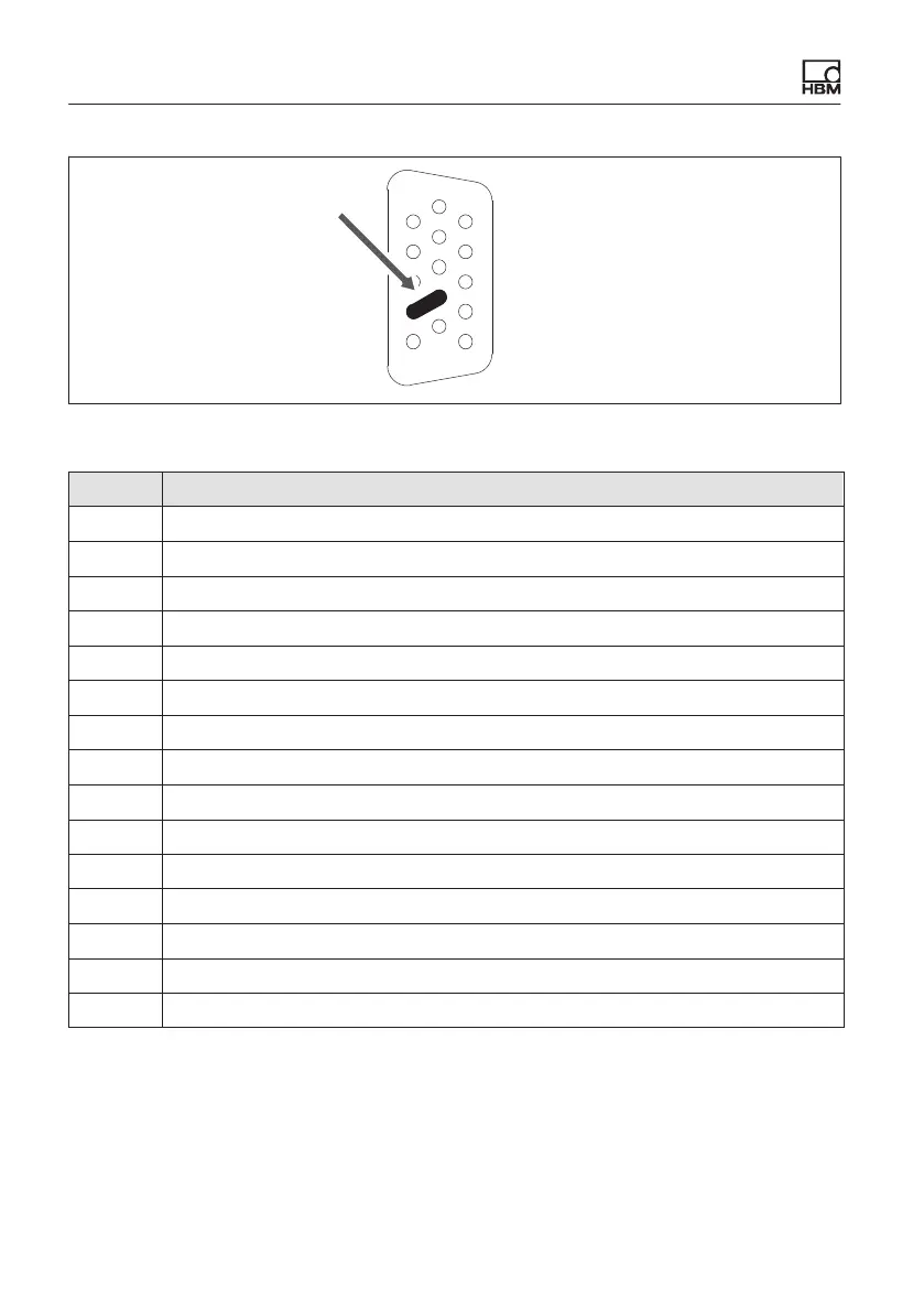
Fig. 8.5 Pin arrangement of connector plug, view from the solder side
Pin Connector
1 TEDS (+)
2 Bridge excitation voltage (-)
3 Bridge excitation voltage (+)
4 Always connect with Pin 9! (Plug-in detection)
5 Measurement signal (+)
6 TEDS (-)
7 Sense lead (-)
8 Sense lead (+)
9 Signal ground
10 Measurement signal (-)
11 Active sensor supply (-)
12 Active sensor supply (+)
13 Current input "30 mA (+)
14 Voltage input 10 V, IEPE (+)
15 Digital output, for external charge amplifier, etc., 5 V/max. 10 mA
The analog output can be tapped via BNC. For configuration instructions see
section 10 "Functions and outputs".