Operating Instructions • Thermal transfer printer TT431 • 03-2019 • 556-00400
Technical data
22
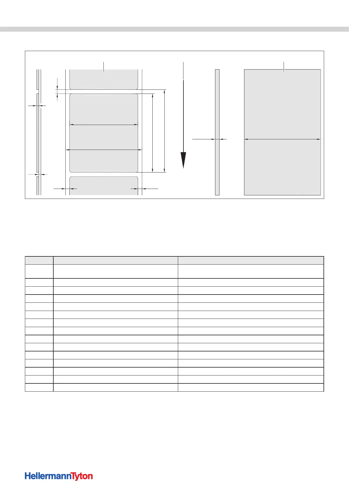
12.2 Sections/continuous material dimensions
QE/QS
(A)
E
F
DL
(DR)
B
C
HV
GE/GS
1 32
Sections/continuous material dimensions.
1 Materials
2 Feed direction
3 Continuous material/heat-shrink tubing
With small and thin materials or strong adhesives, there can be limitations. Critical uses must be tested and approved.
f Observe the bending stiffness The material must be able to follow the print roller.
Dimension Name Dimension in mm
B
Material width
for multi-track material
10 - 116
5 - 57
H Material height 5 - 1000
- Tear-off length > 30
- Cut length > 5
A Material distance > 2
C Wide carrier material 9 - 120
GE Continuous material width 9 - 120
GS Wide heat-shrink tubing 5 - 85
DL Left margin ≥ 0
DR Right margin ≥ 0
E Material thickness 0.03 - 0.60
F Carrier material thickness 0.03 - 0.16
QE Continuous material thickness 0.05 - 0.50
QS Heat-shrink tubing thickness ≤ 1.1
V Feed >= 7
 Loading...