90 UDC3300 Limit Controller Product Manual 1/01
7.8 Parts Replacement Procedures, Continued
Communications
board
Follow the procedure listed in Table 7-18 to replace the following boards:
• DMCS Communications Board—P/N 30756690-501
• RS422/485 Communications Board—P/N 30756693-501
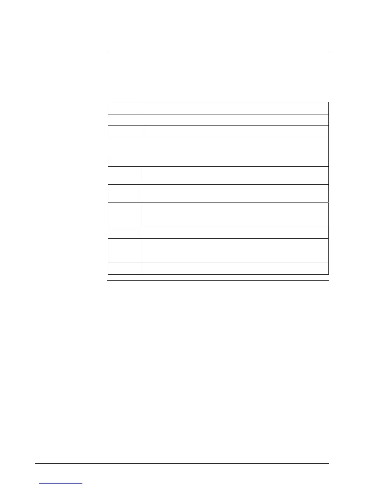
Table 7-18 Communications Board Replacement Procedure
Step Action
1
Remove the chassis from the case. See Figure 7-1.
2
Remove the printed wiring boards from the chassis. See Figure 7-3.
3
Lay the boards flat and identify the Communications board. See Figure
7-4.
4
Remove the transformer plug from connector J8.
5
Locate the three mounting posts under the MCU/Output board that attach
the Communications board to the MCU/Output board.
6
Use small pliers and squeeze the ends of each post together and push it
up through the board. Remove the Communications board.
7
Orient the new Communications board onto the MCU/Output board and
push the mounting posts down through the MCU/Output board until they
click into place.
8
Replace the transformer plug onto connector J8.
9
Slide the printed wiring boards back into the chassis. Make sure the
connections to the keyboard assembly are made and that the release
points on the chassis snap into place on the printed wiring boards.
10
Reinstall the chassis into the case. Push in hard, then tighten the screw.
Continued on next page

 Loading...


