1/01 UDC3300 Limit Controller Product Manual 15
2.5 Wiring Diagrams, Continued
Output and alarm
wiring diagram
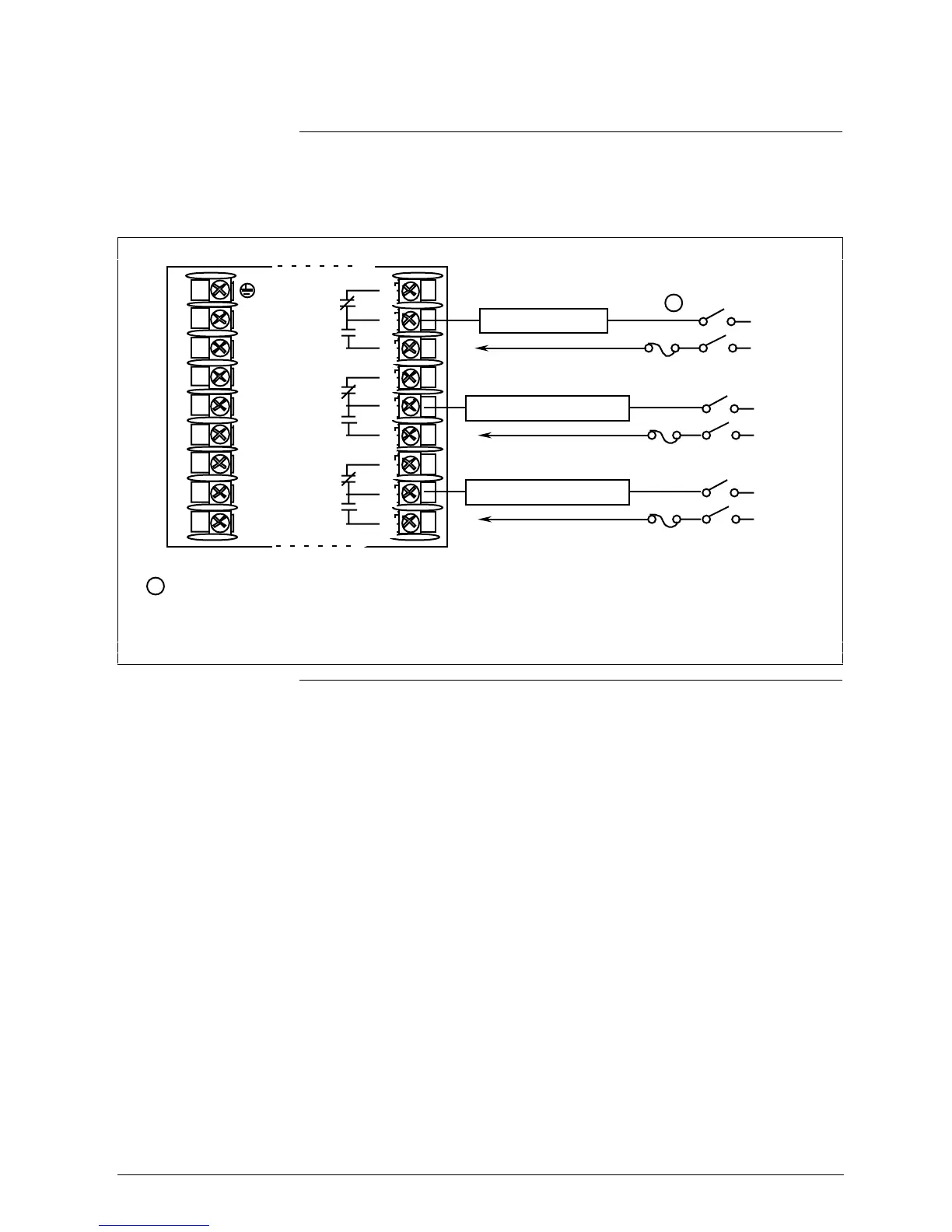
Figure 2-7 shows the Output and Alarm wiring connections for Limit
controllers.
Figure 2-7 Output and Alarm Wiring
Alarm
Relay #1
Non-Latching
To terminal
7 or 9
Alarm
Relay #2
Non-Latching
To terminal
4 or 6
Output
Relay #1
Latching
L1
L2/N
22
23
24
25
26
27
1
2
3
4
5
6
7
8
9
Limit Relay Load
To terminal
1 or 3
1
1
Electromechanical relays are rated at 5 Amps @ 120 Vac or 2.5 Amps at 240 Vac.
Customer should size fuses accordingly.
Alarm Relay #2 Load
Load
Supply
Power
Load
Supply
Power
Alarm Relay #1 Load
Load
Supply
Power
22645
N.C.
N.O.
N.O.
N.C.
N.O.
N.C.
Continued on next page

 Loading...


