14 UDC3300 Limit Controller Product Manual 1/01
2.5 Wiring Diagrams, Continued
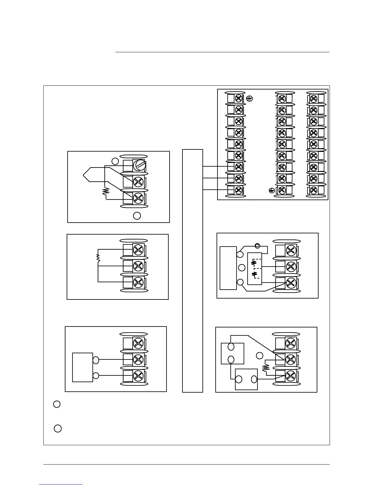
Input #1 connections
Figure 2-6 shows the wiring connections for Input #1.
Figure 2-6 Input #1 Connections
1
2
3
4
5
6
7
8
9
10
11
12
13
14
15
16
17
L1
L2/N
22
23
24
25
26
27
R
+
–
I
N
P
U
T
1
25
26
27
Use Thermocouple
extension wire only
Thermocouple
25
26
27
RTD
25
26
27
MV or Volts
except 0 –10 Volts
MV or Volt
source
25
26
27
0 –10 Volts
25
26
27
+
–
4–20 milliamps
R
–
+
Power
Supply
–
+
Xmitter
+
–
250 Ω
+
–
1
2
3
–
0–10
Volt
source
+
+
–
R
R
+
R
–
R
+
–
100K
100K
The 250Ω load resistor for 4-20mA or the Voltage divider for 0–10 Volts or the 500 Ohm
C/J compensation resistor are supplied with the controller when the input is specified.
These items must be installed when you wire the controller before startup.
1
1
1
1
Remove screw and
install C/J on the "R" terminal,
connect tang to "–" terminals.
2
2 When installing the cold junction (Part number 30757088-001) for a T/C input, remove the screws from
terminals 25 and 27, and install the assembly into place.
22608
Continued on next page

 Loading...


