1/01 UDC3300 Limit Controller Product Manual 27
3.8 Input 1 Parameters Set Up Group
Introduction
This data deals with various parameters required to configure Input 1.
Function prompts
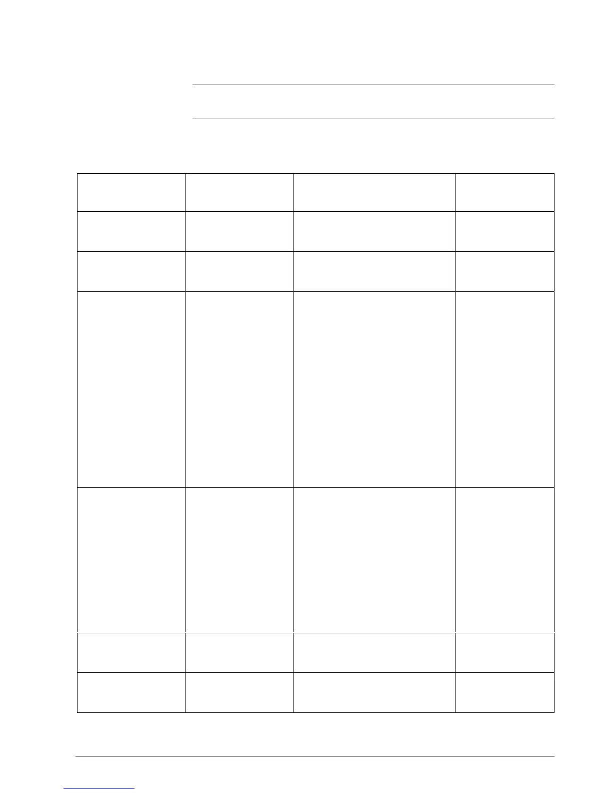
Table 3-5 lists all the function prompts in the “INPUT 1” Set Up group.
Table 3-5 Input 1 Group Function Prompts
Function Prompt
Lower Display
Function
Name
Selections or
Range of Setting
Upper Display
Factory Setting
DECIMAL
Decimal Point Location XXXX None
XXX.X One
XX.XX Two
XXXX
UNITS
Temperature Units DEG F
DEG C
NONE
NONE
IN1 TYPE
Input 1 Actuation Type B TC T TC L
E TC H W TC H
E TC L W TC L
J TC H 100 PT
J TC L 100 LO
K TC H 200 PT
K TC L 500 PT
NNM H RAD RH
NNM L RAD RI
NM90 H 0-20mA*
NM90 L 4-20mA*
NIC TC 0-10mV*
R TC 0-50mV*
S TC 0-5 V*
T TC H 1-5 V*
0-10V*
*not available for FM models
0-10mV
(K TC H for FM only)
XMITTER
(not available for FM
models)
Transmitter
Characterization
B TC S TC
E TC H T TC H
E TC L T TC L
J TC H W TC H
J TC L W TC L
K TC H 100 PT
K TC L 100 LO
NNM H 200 PT
NNM L 500 PT
NM90 H RAD RH
NM90 L RAD RI
NIC TC LINEAR
R TC SQROOT
LINEAR
IN1 HI
Input 1 High Range
Value (Linear Inputs and
Radiamatic RI only)
–999. to 9999.
in engineering units
1000
(2400 for FM only)
IN1 LO
Input 1 Low Range
Value (Linear Inputs and
Radiamatic RI only)
–999. to 9999.
in engineering units
0
Continued on next page

 Loading...


