1/01 UDC3300 Limit Controller Product Manual 3
1.2 Operator Interface
Displays and
indicators
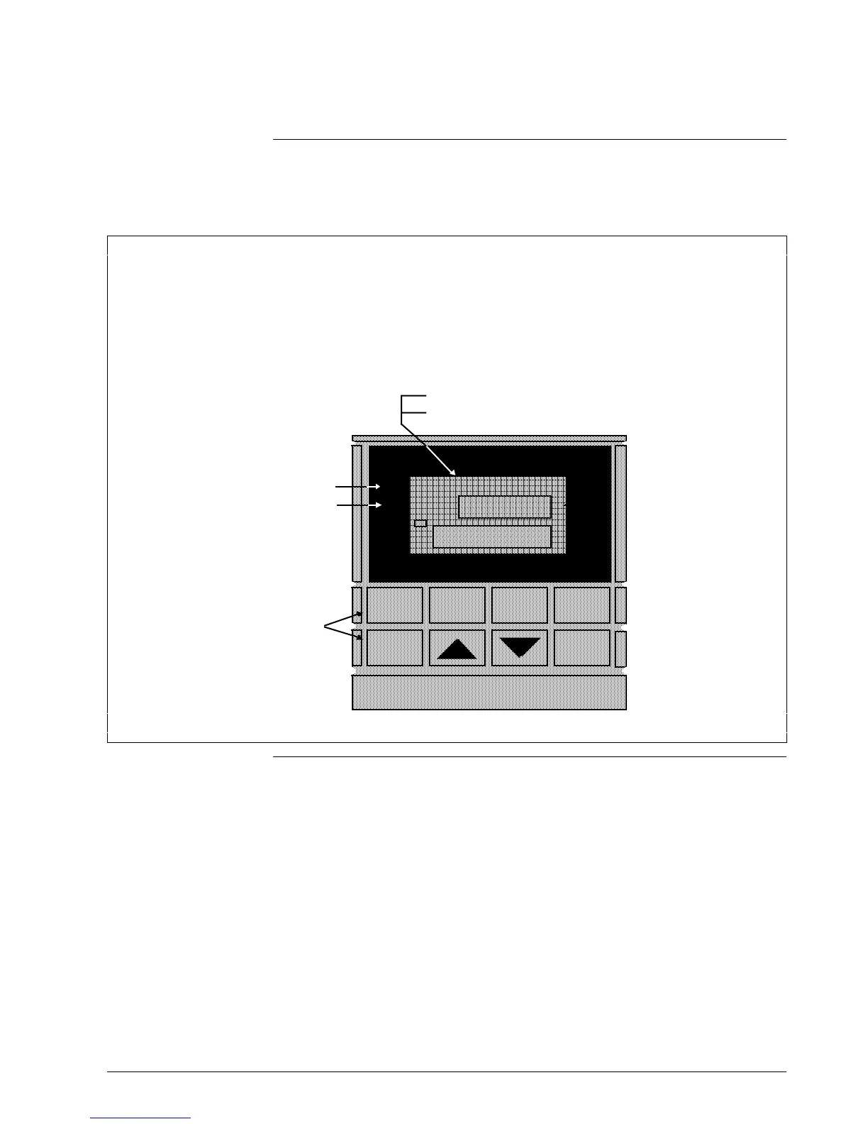
Figure 1-1 shows the operator interface and defines the displays and
indicators. The function of the keys is shown in Table 1-1.
Figure 1-1 Operator Interface Displays and Indicators
Upper Display - Six Characters
• Normal Operation - four digits dedicated to display the process variable, or blank
• Configuration Mode - displays parameter value or selection
Lower Display - Eight characters
• Normal Operation - displays the value of limit control setpoint, or indicates "LIMIT OK". When alarm
condition exists, it alternates between the setpoint value and the word "LIMIT".
• Configuration Mode - displays function group and parameters
ALM
DI
RSP
OUT
1
1
1 2
F C
FUNCTION
SET UP
LOWER
DISPLAY
Indicator definition when lit
ALM - Alarm conditions exist
DI - Digital Input active
F - °Fahrenheit being used
C - °Centigrade being used
Keys - See Table 1-1
RESET
22642
Continued on next page

 Loading...


