54 UDC3300 Limit Controller Product Manual 1/01
5.6 Alarm Setpoints
Introduction
An alarm consists of a relay contact and an operator interface indication.
The alarm is de-energized if Setpoint 1 or Setpoint 2 is exceeded. The
alarm is energized when the monitored value goes into the allowed region
by more than the hysteresis.
The relay contacts can be wired for normally open (NO) or normally
closed (NC) at the rear terminals. See Section 2 — Installation for details.
There are four alarm setpoints, two for each alarm. The type and state
(High or Low) is selected during configuration. See Section 3 —
Configuration for details.
Procedure for
displaying and
changing the alarm
setpoints
The procedure for displaying and changing the alarm setpoints is listed in
Table 5-7.
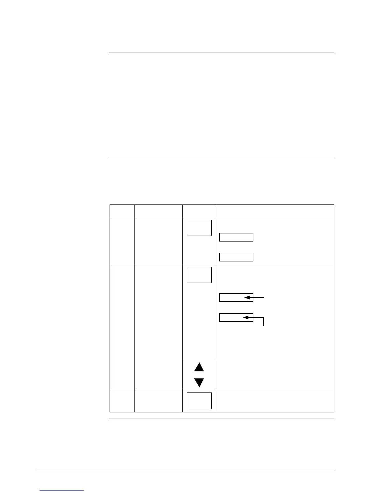
Table 5-7 Procedure for Displaying or Changing the Alarm Setpoints
Step Operation Press Action
1
Access the
Alarm Set Up
group
SET UP
Until you see:
ALARMS
Lower Display
SET UP
Upper Display
2
Access the
Alarm Setpoint
Values
FUNCTION
until you see the desired alarm setpoint and
its value. The specific prompts are shown
below.
Lower Display
Upper Display
The alarm setpoint
value
A1S1 VAL = (Alarm 1, Setpoint 1 value)
A1S2 VAL = (Alarm 1, Setpoint 2 value)
A2S1 VAL = (Alarm 2, Setpoint 1 value)
A2S2 VAL = (Alarm 2, Setpoint 2 value)
or
to change any alarm setpoint value you
select in the upper display.
3
Return to normal
operation
LOWER
DISPLAY

 Loading...


