1/01 UDC3300 Limit Controller Product Manual 59
6.3 Preliminary Information
Calibration steps
Use the following steps when calibrating an input.
Step Action
1 Find the minimum and maximum range values for your PV input
range from Table 6-1.
2 Disconnect the field wiring and find out what equipment you will need
to calibrate. DO NOT remove external resistor assemblies (if
present).
3 Wire the calibrating device to your controller according to the Set Up
wiring instructions for your particular input.
4 Follow the calibration procedure given for Input #1 after the controller
has warmed up for a minimum of 15 minutes.
Disconnect the field
wiring
Tag and disconnect any field wiring connected to the input terminals on
the rear of the controller.
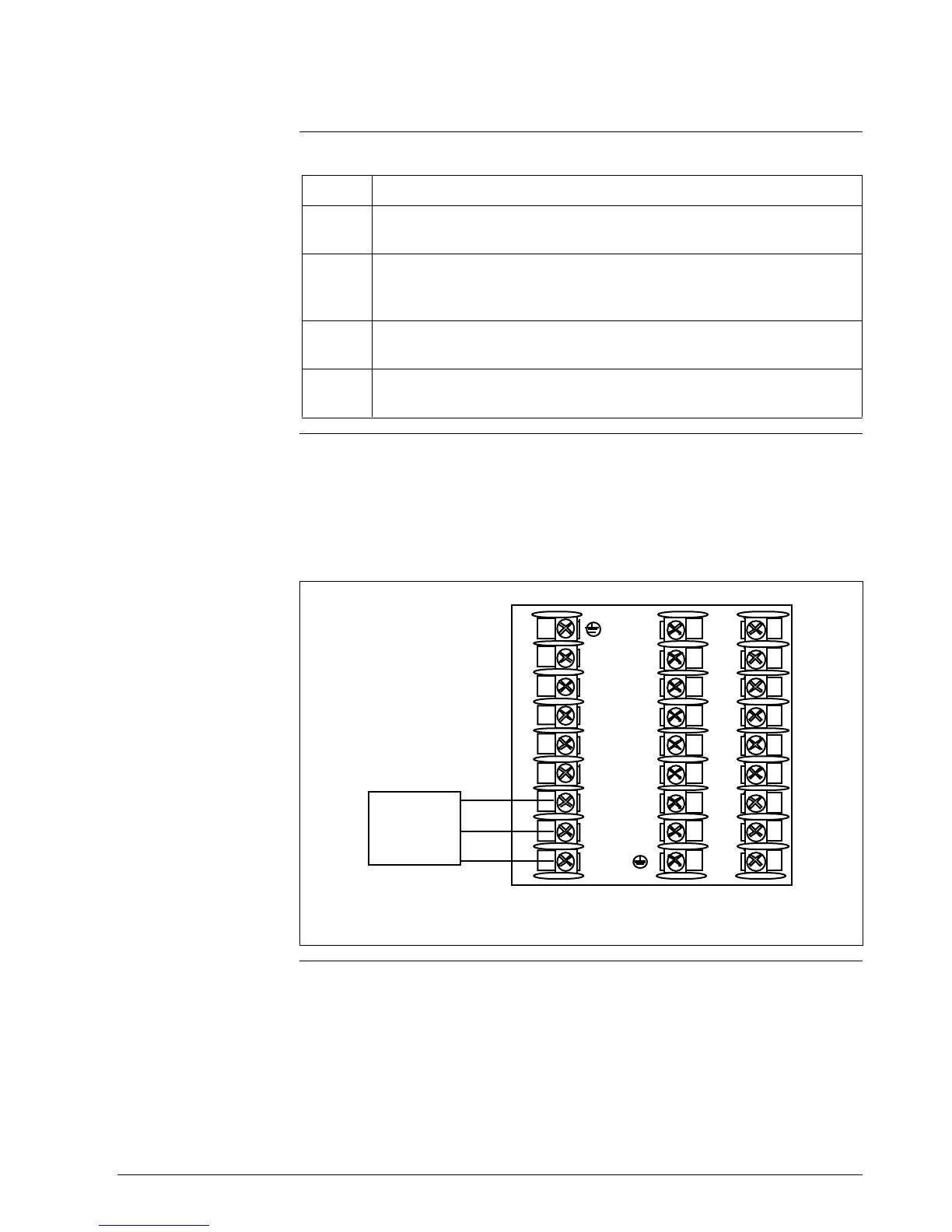
Figure 6-1 shows the wiring terminal designations for Input #1.
Figure 6-1 Input #1 Wiring Terminals
1
2
3
4
5
6
7
8
9
L1
L2/N
22
23
24
25
26
27
10
11
12
13
14
15
16
17
R
+
–
Input 1
connections
22648
Continued on next page

 Loading...


