1/01 UDC3300 Limit Controller Product Manual 7
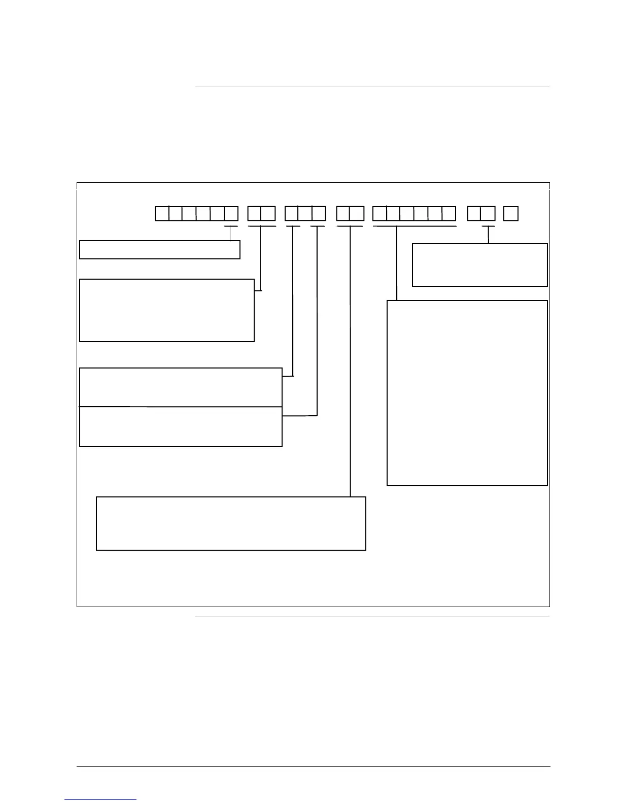
2.2 Model Number Interpretation
Model number
The model number interpretation is shown in Figure 2-1. Write the model
number into the spaces provided and compare it to the model number
interpretation. This information will also be useful when you wire your
controller.
Figure 2-1 Model Number Interpretation
0DC3 3 0
Table VITable VTable IVTable IIITable IITable IKey Number
Output #1
E – =
Output #2 or Alarm #2
– 0 =
– E =
Limit Control Model
Relay, Electromechanical
None
Relay, Electromechanical
External Interface
0 –– =
1 –– =
Digital Inputs
–– 0 =
–– 3 =
None
RS422/485 ASCII
None
One Digital Input
PV Input
1 – =
2 – =
3 – =
T/C, RTD, Radiamatic, mV, 0-5V, 1-5V
T/C, RTD, Radiamatic, mV, 0-5V, 1-5V, 0-20 mA, 4-20 mA
T/C, RTD, Radiamatic, mV, 0-5V, 1-5V, 0-20 mA, 4-20 mA, 0-10V
Options
0 ––––– =
1 ––––– =
– 0 –––– =
– F –––– =
––0 ––– =
–– B ––– =
–– T ––– =
––– 0 –– =
––– T –– =
–––– 0 – =
–––– D – =
––––– 0 =
90 to 264 Vac Power
24 Vac/dc Power
None
FM and UL*
Gray Elastomer Bezel
Blue Elastomer Bezel
Tan Elastomer Bezel
None
Customer ID Tag
None
DIN Cutout Adapter
None
Certificate
– 0 =
– C =
None
Certificate of Conformance
L00 0
*FM approved Limit Controllers are restricted to thermocouple and RTD PV inputs.
Limit Controllers are UL recognized for regulatory use only.
– A –––– = CSA, FM and UL*
––– P –– = Rear Terminal Cover
––– U –– = Rear Terminal Cover
and Tag

 Loading...


