88 UDC3300 Limit Controller Product Manual 1/01
7.8 Parts Replacement Procedures, Continued
Power input board
Follow the procedure listed in Table 7-16 to replace the Power Input
board—P/N 51309404-502 (90 to 264 Vac) or 51309404-501 (24 Vac/dc).
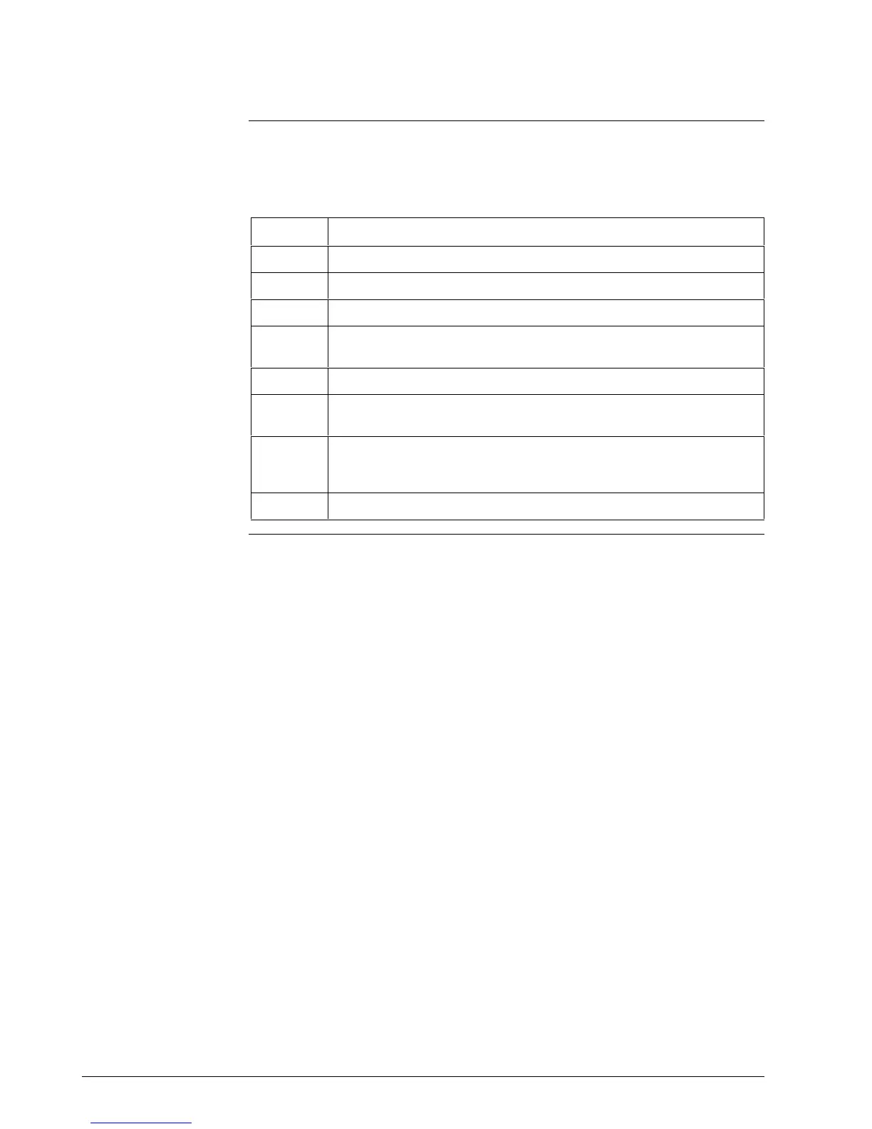
Table 7-16 Power Input Board Replacement Procedure
Step Action
1
Remove the chassis from the case. See Figure 7-1.
2
Remove the printed wiring boards from the chassis. See Figure 7-3.
3
Lay the boards flat and identify the Power Input board. See Figure 7-4.
4
Remove the transformer connections to the Digital Input board and
Communications board, if present.
5
Replace the Power Input board.
6
Reinstall the transformer connections to Digital Input board and
Communications board, if present.
7
Slide the printed wiring boards back into the chassis. Make sure the
connections to the display/keyboard assembly are made and that the
release points on the chassis snap into place on the printed wiring boards.
8
Reinstall the chassis into the case. Push in hard, then tighten screw.
Continued on next page

 Loading...


