102 UDC3300 Limit Controller Product Manual 1/01
9.6 Noise Suppression at the Source, Continued
Inductive coils,
continued
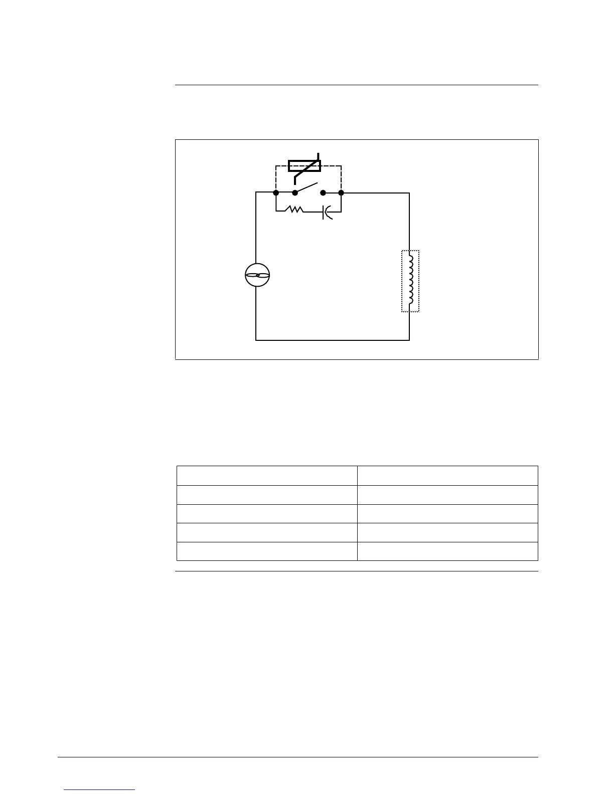
Figure 9-2 is an illustration of transient suppression in inductive coils.
Figure 9-2 Transient Suppression in Inductive Coils
A.C.
supply
Inductive
load
R
C
MOV
20781
Additional protection may be provided by adding an RC circuit in parallel
with the MOV. This consists of a 220-ohm resistor in series with a 0.5
microfarad, 1000V capacitor. The power rating of the resistor will depend
on the voltage rating of the coil (see Table 9-3).
Table 9-3 Coil Voltage vs Resistor Voltage Rating
Coil Voltage Resistor Voltage Rating
115V 1/4 Watt
230V 1 Watt
460V 3 Watt
550V 5 Watt
Continued on next page

 Loading...


