86 UDC3300 Limit Controller Product Manual 1/01
7.8 Parts Replacement Procedures, Continued
How to remove the
printed wiring boards
from the chassis
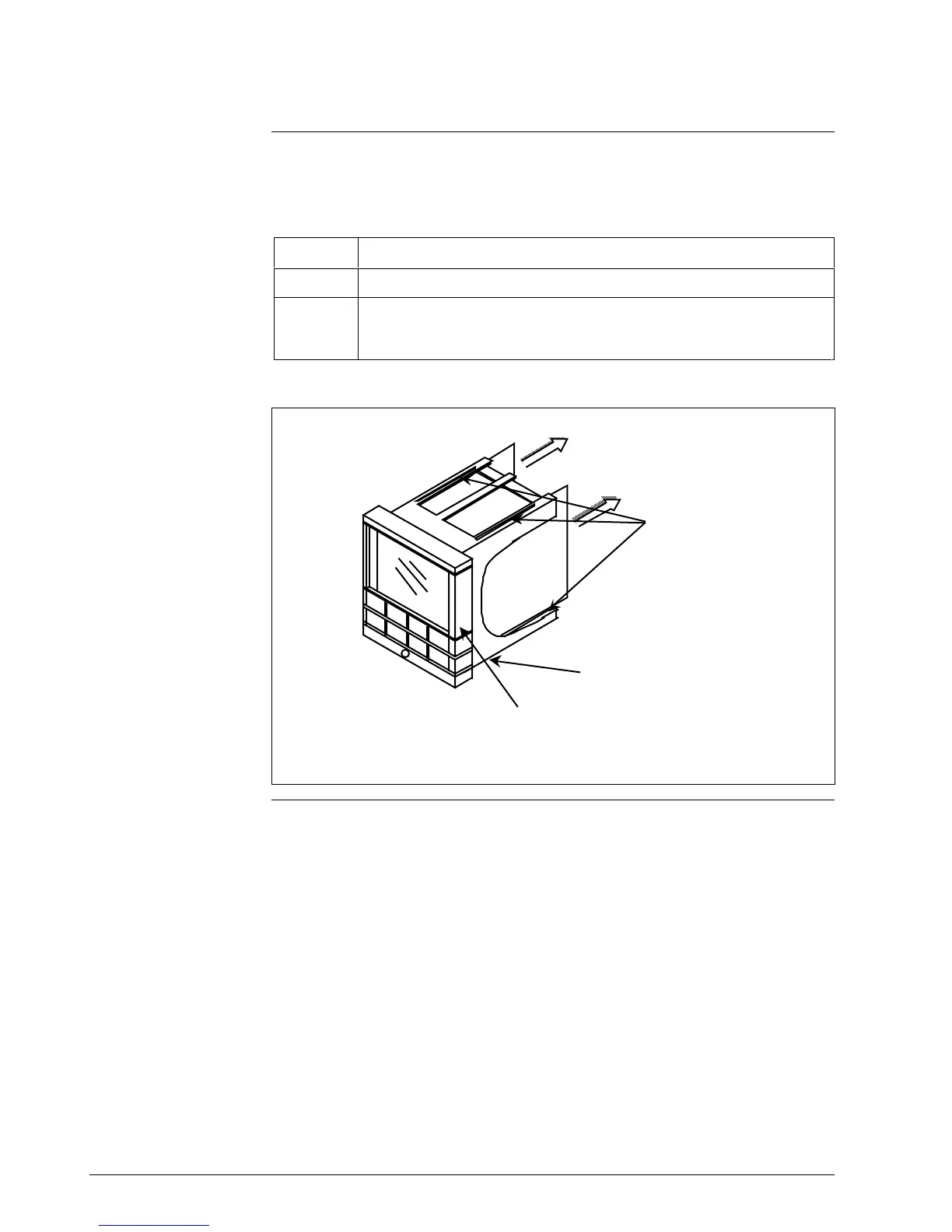
To remove the printed wiring boards from the chassis, refer to Figure 7-3
and follow the procedure in Table 7-15.
Table 7-15 Printed Wiring Board Removal from Chassis
Step Action
1
Remove the chassis from the case as shown in Figure 7-1.
2
Separate the chassis frame at the release points shown in Figure 7-3 and
wiggle each printed wiring board out of its socket on the display/keyboard
assembly. Pull both boards out of the chassis assembly.
Figure 7-3 Removing the Printed Wiring Boards
Pull printed
wiring boards out
of chassis
Printed wiring
boards
release points
Chassis assembly
Rubber bezel
and window
22639
Continued on next page

 Loading...


