12 UDC3300 Limit Controller Product Manual 1/01
2.5 Wiring Diagrams
Composite wiring
diagram
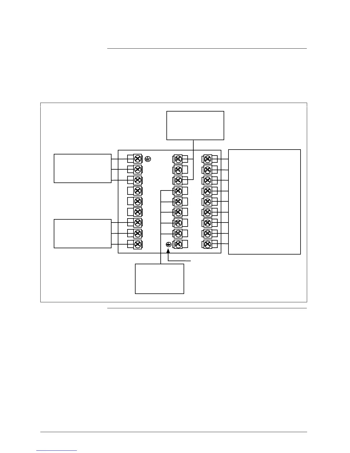
Figure 2-4 is a composite wiring diagram of the UDC3300 Limit
controller. It identifies the terminal designations and their functions. Refer
to the individual diagrams listed to wire the controller according to your
requirements.
Figure 2-4 Composite Wiring Diagram
1
2
3
4
5
6
7
8
9
L1
L2/N
22
23
24
25
26
27
Communications
Terminals
See Figures 2-9
and 2-10
Outputs and Alarms
Terminals
See Figure 2-7
Digital Input
Terminals
See Figure 2-8
AC Line Voltage
Terminals
See Figure 2-5
Input #1
Terminals
See Figure 2-6
10
11
12
13
14
15
16
17
I/O Shield Ground
(Do Not use for communication shield)
Continued on next page

 Loading...


