1/01 UDC3300 Limit Controller Product Manual 11
2.4 Wiring, Continued
Alarm circuit wiring
The insulation of wires connected to the Alarm terminals shall be rated for
the highest voltage involved. Extra Low Voltage (ELV) wiring (input,
current output, and low voltage Alarm circuits) shall be separated from
HAZARDOUS LIVE (>30 Vac, 42.4 Vpeak, or 60 Vdc) wiring per Table
2-2.
Identify your wiring
requirements
To determine the appropriate diagrams for wiring your controller, refer to
the model number interpretation in this section. The model number of the
controller can be found on the inside of the case.
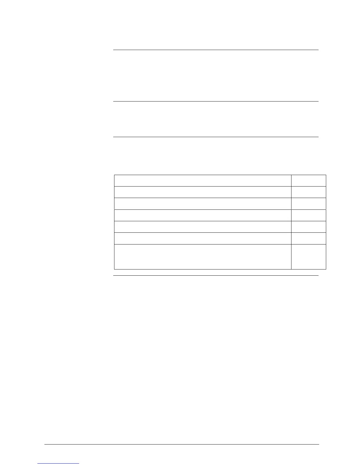
Wiring the controller
Using the information contained in the model number, select the
appropriate wiring diagrams from the figures listed below and wire the
controller accordingly.
Wiring Requirements Figure
Composite Wiring Diagram 2-4
Line Power 90–264 Vac or 24 Vac/dc 2–5
Input #1 Wiring 2–6
Output and Alarm Wiring 2-7
Digital Inputs Wiring 2–8
Communications Wiring
• RS422
• DMCS
2–9
2–10

 Loading...


