105
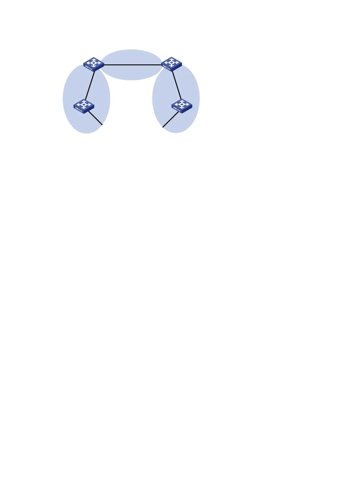
Figure 24 Network diagram
Configuration procedure
1. Configure IP addresses for interfaces. (Details not shown.)
2. Enable OSPF:
# Configure Switch A.
<SwitchA> system-view
[SwitchA] router id 10.2.1.1
[SwitchA] ospf
[SwitchA-ospf-1] area 0
[SwitchA-ospf-1-area-0.0.0.0] network 10.1.1.0 0.0.0.255
[SwitchA-ospf-1-area-0.0.0.0] quit
[SwitchA-ospf-1] area 1
[SwitchA-ospf-1-area-0.0.0.1] network 10.2.1.0 0.0.0.255
[SwitchA-ospf-1-area-0.0.0.1] quit
[SwitchA-ospf-1] quit
# Configure Switch B.
<SwitchB> system-view
[SwitchB] router id 10.3.1.1
[SwitchB] ospf
[SwitchB-ospf-1] area 0
[SwitchB-ospf-1-area-0.0.0.0] network 10.1.1.0 0.0.0.255
[SwitchB-ospf-1-area-0.0.0.0] quit
[SwitchB-ospf-1] area 2
[SwitchB-ospf-1-area-0.0.0.2] network 10.3.1.0 0.0.0.255
[SwitchB-ospf-1-area-0.0.0.2] quit
[SwitchB-ospf-1] quit
# Configure Switch C.
<SwitchC> system-view
[SwitchC] router id 10.4.1.1
[SwitchC] ospf
[SwitchC-ospf-1] area 1
[SwitchC-ospf-1-area-0.0.0.1] network 10.2.1.0 0.0.0.255
[SwitchC-ospf-1-area-0.0.0.1] network 10.4.1.0 0.0.0.255
[SwitchC-ospf-1-area-0.0.0.1] quit
[SwitchC-ospf-1] quit
# Configure Switch D.
Area 0
Area 1
Area 2
Switch C
Vlan-int100
10.1.1.2/24
Vlan-int100
10.1.1.1/24
Vlan-int300
10.4.1.1/24
Vlan-int200
10.2.1.2/24
Switch B
Vlan-int200
10.3.1.1/24
Vlan-int200
10.3.1.2/24
Switch A
Vlan-int200
10.2.1.1/24
Vlan-int300
10.5.1.1/24
Switch D
 Loading...


